Yamaha D24 Owner's Manual - Page 188
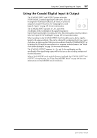
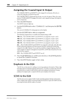
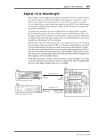
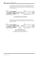
Digital I/O & Wordlength
 |
View all Yamaha D24 manuals
Add to My Manuals
Save this manual to your list of manuals |
Page 188 highlights
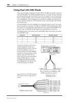
Digital I/O & Wordlength 189 Digital I/O & Wordlength When a high-resolution digital audio signal is transferred to a lower-resolution system, care must be taken to ensure that the digital audio samples are truncated correctly. When a 24-bit signal is transferred directly to a 16-bit DAT recorder, for example, low-level detail is lost when the eight least-significant bits (LSB) of each audio sample are discarded, resulting in distortion and a grainy sound. The greater the truncation, the greater the distortion. To optimize the truncation process, a technique known as digital dither is applied before feeding the signal to the lower-resolution system. Digital dither works by comparing the output of a special pseudorandom number sequence generator with the lowest data bit of the shortened audio sample and the unwanted bits. The lowest bit is then rounded up or down prior to D/A conversion. Digital dither endows the digital signal with a noise signal (hiss) close to the minimum theoretical limit, which is around -96 dB for a 16-bit signal, although this is considered to be less offensive than the distortion caused by truncating without dither. To minimize the noise, some digital audio processors use noise-shaping techniques to shift it into areas of the audio spectrum where the ear is less sensitive. Unless you have a specific reason for not using it, digital dither should be used when transferring high-resolution signals to lower-resolution systems. In the following system, a 24-bit recording resolution is used for multitrack recording on the D24, and a 16-bit resolution for stereo recording on the DAT. The digital dither function on the digital mixing console is set accordingly. D24 OVER -dB 0 2 6 10 12 14 20 18 30 20 42 26 60 READY 1 2 3 4 5 RECORD READY SOLO/ SELECT PEAK HOLD AUTO INPUT ALL INPUT MONITOR SELECT OVER 0 -dB 2 6 12 20 30 42 60 READY 0 0 0 0 0 0 0 0 ABS H M S F YAMAHA D24 LOCK WC INT FS 48K BIT 24 TC MASTER L R 6 7 8 7 8 9 PROJECT SELECT 4 5 6 LOC MEM RECALL FORMAT CHASE 1 2 3 LOC MEM STORE 0/- CANCEL ENTER LOCATE TIME DISPLAY CAPTURE ABS/REL REMAIN VARI SPEED UTILITY SETUP V. TRACK SELECT EDIT UNDO/ REDO JOG ON DIGITAL MULTITRACK RECORDER PROJECT SEARCH LAST REC IN OUT SET AUTO PUNCH RTN TO ZERO ROLL BACK A B REPEAT REHE AB REW FF STOP PLAY REC JOG/DATA SHUTTLE/ CURSOR POWER ON OFF 0 10 PHONES LEVEL PHONES Recording resolution: 24-bit 02R AES/EBU (24-bit) mYGDAI YGDAI (SLOT 1) DAT 00.00.00.00 DAT Recording resolution: 16-bit S/PDIF (16-bit) Digital input DIGITAL STEREO COAXIAL OUT Slot Output Select SLOT 1: Bus 1-8 Dither setup BUS 1-8: 24-bit Stereo out: 16-bit D24-Owner's Manual
-
 1
1 -
2
-
3
-
4
-
5
-
6
-
7
-
8
-
9
-
10
-
11
-
12
-
13
-
14
-
15
-
16
-
17
-
18
-
19
-
20
-
21
-
22
-
23
-
24
-
25
-
26
-
27
-
28
-
29
-
30
-
31
-
32
-
33
-
34
-
35
-
36
-
37
-
38
-
39
-
40
-
41
-
42
-
43
-
44
-
45
-
46
-
47
-
48
-
49
-
50
-
51
-
52
-
53
-
54
-
55
-
56
-
57
-
58
-
59
-
60
-
61
-
62
-
63
-
64
-
65
-
66
-
67
-
68
-
69
-
70
-
71
-
72
-
73
-
74
-
75
-
76
-
77
-
78
-
79
-
80
-
81
-
82
-
83
-
84
-
85
-
86
-
87
-
88
-
89
-
90
-
91
-
92
-
93
-
94
-
95
-
96
-
97
-
98
-
99
-
100
-
101
-
102
-
103
-
104
-
105
-
106
-
107
-
108
-
109
-
110
-
111
-
112
-
113
-
114
-
115
-
116
-
117
-
118
-
119
-
120
-
121
-
122
-
123
-
124
-
125
-
126
-
127
-
128
-
129
-
130
-
131
-
132
-
133
-
134
-
135
-
136
-
137
-
138
-
139
-
140
-
141
-
142
-
143
-
144
-
145
-
146
-
147
-
148
-
149
-
150
-
151
-
152
-
153
-
154
-
155
-
156
-
157
-
158
-
159
-
160
-
161
-
162
-
163
-
164
-
165
-
166
-
167
-
168
-
169
-
170
-
171
-
172
-
173
-
174
-
175
-
176
-
177
-
178
-
179
-
180
-
181
-
182
-
 183
183 -
 184
184 -
 185
185 -
 186
186 -
 187
187 -
 188
188 -
 189
189 -
 190
190 -
 191
191 -
 192
192 -
 193
193 -
194
-
195
-
196
-
197
-
198
-
199
-
200
-
201
-
202
-
203
-
204
-
205
-
206
-
207
-
208
-
209
-
210
-
211
 |
 |