Yamaha EMX5014C Owner's Manual - Page 20
INSERT I/O Jack Channels 1 to 6, 26 dB] Switch Channels 1 to 6, GAIN Control
 |
UPC - 086792838274
View all Yamaha EMX5014C manuals
Add to My Manuals
Save this manual to your list of manuals |
Page 20 highlights
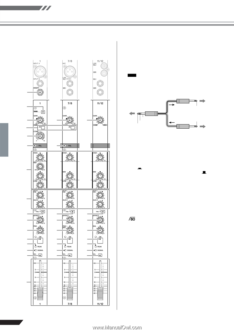
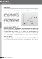
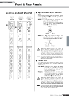
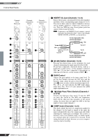
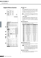
Reference Front & Rear Panels Channels 1 to 6 (Monaural) Channels 7/8 and 9/10 (Stereo) Channels 11/12 and 13/14 (Stereo) 3 4 5 5 5 6 7 8 8 9 0 A A A B B B C C C D D D E E E F F F G G G H 3 INSERT I/O Jack (Channels 1 to 6) Each of these jacks is positioned between the equalizer and fader of the corresponding input channel (1 to 6). You can use these jacks to connect channels to devices such as graphic equalizers, compressors, and noise filters. These are TRS (tip, ring, sleeve) phone jacks that support bidirectional operation. NOTE Connection to an INSERT I/O jack requires a special separately-sold insertion cable-such as the Yamaha YIC025, YIC050, or YIC070-as shown below. To the input jack of the external processor To the INSERT I/O jack Tip:OUT SSleleeevvee(G(Grorouunndd)) Ring :IN Tip:OUT Tip:IN To the output jack of the external processor 4 [26 dB] Switch (Channels 1 to 6) Pressing this button turns on the attenuator for each channel, attenuating the input signal level by 26 dB. If you have connected a line-level device, such as a keyboard or audio device, set the channel's switch to ON ( ). If you have connected a microphone or other mic-level device, set the switch to OFF ( ). 5 GAIN Control Adjusts the gain applied to the input signal level. To get the best balance between the S/N ratio and the dynamic range, adjust the gain so that the PEAK indicator E comes on only at about maximum input level. The -60 to -16 scale indicates the MIC input adjustment level. The -34 to 10 scale indicates the LINE input adjustment level. 6 (High Pass Filter) Switch (Channels 1 to 9/10) Switches the high pass filter on/off. To turn the HPF on, press this switch in. The HPF cuts frequencies below 80 Hz. (But note that regardless of the switch setting, the mixer does not apply this HPF to the line inputs of stereo input channels.) 7 COMP knob (Channels 1 to 6) This knob adjusts the level of compression applied to the channel. As the knob is turned to the right, the mixer automatically raises the compression ratio while adjusting the output gain accordingly. The result is a narrower, more even dynamic range, as louder signals are softened while the overall level is boosted. Avoid setting the knob too high, however, as excess compression may lead to howling. 20 EMX5014C Owner's Manual
-
 1
1 -
2
-
3
-
4
-
5
-
6
-
7
-
8
-
9
-
10
-
11
-
12
-
13
-
14
-
 15
15 -
 16
16 -
 17
17 -
 18
18 -
 19
19 -
 20
20 -
 21
21 -
 22
22 -
 23
23 -
 24
24 -
 25
25 -
26
-
27
-
28
-
29
-
30
-
31
-
32
-
33
-
34
-
35
-
36
-
37
 |
 |