Yamaha EMX5014C Owner's Manual - Page 21
Equalizer HIGH, MID, and LOW, FCL Feedback Channel Locating lamp - setup
 |
UPC - 086792838274
View all Yamaha EMX5014C manuals
Add to My Manuals
Save this manual to your list of manuals |
Page 21 highlights
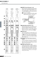
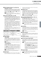
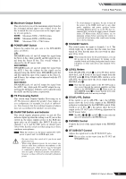
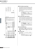
Reference Front & Rear Panels 8 FCL (Feedback Channel Locating) lamp (Channels 1 to 9/10) This lamp is used during setup to identify any channel that might be howling. Check these lamps when setting up for a performance. If the lamp lights up, adjust the channel's equalizer 9 or channel fader H to reduce the level so that the lamp goes off. NOTE Input of a continuous sound (as from a CD player or vocal) may cause the lamp to come on even in the absence of howling. 9 Equalizer (HIGH, MID, and LOW) This three-band equalizer adjusts the channel's high, mid, and low frequency bands. Setting the knob to the " " position produces a flat frequency response for the corresponding frequency band. Turning the knob to the right boosts the corresponding frequency band, while turning to the left attenuates the band. On channels 1 to 6, the MID range is controlled by two knobs. The upper knob sets the center frequency for the mid range, while the lower knob sets the attenuation (counterclockwise) or boost (clockwise) for the range. (Again, setting the lower knob to " " produces a flat response.) On stereo channel pairs 7/8 to 13/14 the mid-range frequency is fixed at 2.5kHz, so only one MID knob is provided. The following table shows the equalization type, the base frequency, and the maximum cut/boost for each of the three bands. Band Type HIGH Shelving MID Peaking LOW Shelving Base Frequency 10 kHz 250 Hz to 5 kHz variable (CHs 1 to 6) 2.5 kHz (CHs 7/8 to 13/14) 100 Hz Maximum Cut/Boost ±15 dB 0 AUX Controls • AUX1 (PRE) This knob adjusts the channel's signal level into the AUX1 bus. The knob should generally be set close to the " " position. On stereo channels, the L (odd) and R (even) input signals are mixed before moving into the AUX bus. NOTE The channel faders do not operate on signals sent to the AUX1 bus. • AUX2 (PRE/POST) This knob adjusts the channel's signal level into the AUX2 bus. The knob should generally be set close to the " " position. Note that you can use the PRE switch A to choose whether to feed the pre-fader or post-fader signal into the AUX2 bus. On stereo channels, the L (odd) and R (even) input signals are mixed before moving into the AUX2 bus. NOTE If the PRE switch is on, the channel's fader will not have any effect on the signal into the AUX2 bus. A PRE Switch Selects whether the pre-fader or the post-fader signal is fed to the AUX2 bus. If the switch is on, the mixer feeds the pre-fader signal to the bus. If off, the mixer feeds the post-fader signal. B EFFECT Knob Adjusts the level of the signal sent from the channel to the EFFECT bus. If input is from a stereo channel pair (7/8, 9/10, 11/12, or 13/14), the signals from the L and R channels are mixed before moving into the bus. The EFFECT bus signal is fed both to the internal digital effector and to the SEND EFF jack I. NOTE The level into the EFFECT bus is affected by the setting of the channel's fader H. C PAN Control (Channels 1 to 6); BAL Control (Channels 7/8 to 13/14) The PAN control determines the positioning of the channel's signal on the Stereo L and R buses. The BAL control sets the balance between left and right channels. Signals into the L input (odd channel) feed to the Stereo L bus; signals into the R input (even channel) feed to the Stereo R bus. NOTE If you are inputting to a stereo channel through the L (MONO) jack only, the BAL knob operates as a PAN knob. D ON Switch Switches the channel on or off. (The indicator lights up if the channel is on.) Be sure to turn on all the channels that you wish to use. If you switch the channel off, you cut off all of its signal feed into the Stereo, AUX, and EFFECT buses. NOTE To reduce noise, turn off all unused channels. E PEAK Indicator Detects the peak level of the post-equalizer signal, and lights up red when the level reaches 3 dB below the clipping level. F SIGNAL Indicator Lights up when a signal is being input into the channel. G PFL (Pre-Fader Listen) Switch Set this switch on to feed the channel's pre-fader signal into the PFL bus, so that it can be monitored at the PHONES jack. To set the switch on, press it in so that it lights up. NOTE • PFL switching and output are not affected by the ON switch. You can monitor the channel's pre-fader signal through the PHONES jack even when the ON switch is set off. • The PFL (G, N, d) and AFL e switches select the mix to be monitored at the PHONES jack. If the channel's PFL or AFL switch is ON, the channel's output is mixed into the monitor signal to the PHONES jack. If both switches are OFF, the channel output is not fed to the PHONES jack. H Channel Fader Adjusts the signal's output level. Use these faders to adjust the volume balance among the various channels. NOTE To reduce noise, set the fader sliders for unused channels all the way down. EMX5014C Owner's Manual 21
-
 1
1 -
2
-
3
-
4
-
5
-
6
-
7
-
8
-
9
-
10
-
11
-
12
-
13
-
14
-
15
-
 16
16 -
 17
17 -
 18
18 -
 19
19 -
 20
20 -
 21
21 -
 22
22 -
 23
23 -
 24
24 -
 25
25 -
 26
26 -
27
-
28
-
29
-
30
-
31
-
32
-
33
-
34
-
35
-
36
-
37
 |
 |
