Yamaha EMX5014C Owner's Manual - Page 25
PHANTOM Switch and Indicator, ST SUB OUT Control - size
 |
UPC - 086792838274
View all Yamaha EMX5014C manuals
Add to My Manuals
Save this manual to your list of manuals |
Page 25 highlights
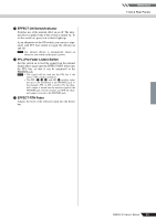
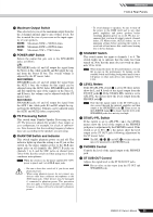
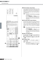
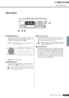
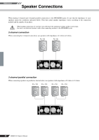
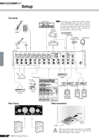
Reference Front & Rear Panels Y Maximum Output Switch This selector lets you set the maximum output from for the 2-channel internal amp to any of three levels. Set this to match the size of your room or the input capacity of your speakers. 500W: Maximum 500W + 500W/4 ohms. 200W: Maximum 200W + 200W/4 ohms. 75W: Maximum 75W + 75W/4 ohms Z POWER AMP Switch Selects the output that gets sent to the SPEAKERS jacks, as follows. L/R: SPEAKERS jacks A1 and A2 output the signal from the Stereo L bus, while jacks B1 and B2 output the signal from the Stereo R bus. The overall volume is adjusted by the ST master fader. AUX1/MONO: SPEAKERS jacks A1 and A2 output the signal from the AUX 1 bus; the volume for this signal can be adjusted using the AUX1 fader. SPEAKERS jacks B1 and B2 output the mix of the signals on the Stereo L and R buses; the volume can be adjusted with the ST master fader. AUX1/AUX2: SPEAKERS jacks A1 and A2 output the signal from the AUX 1 bus, while jacks B1 and B2 output the signal from the AUX2 bus. Volumes can be adjusted using the AUX1 and AUX2 faders, respectively. [ YS Processing Switch This switch turns Yamaha Speaker Processing on or off. The processor adjusts the speaker's bass ranges so as to compensate, for example, for a lack of subwoofers. Note however that the resulting frequency balance may vary according to the speakers you are using. \ PHANTOM Switch and Indicator This switch toggles phantom power on and off. The indicator lights up when the setting is on. If you set the switch on, the mixer supplies power to the XLR mic input jacks on all channels (the INPUT B jacks on channels 1 to 6, and the MIC jacks on channel pairs 7/8 to 9/10). Set this switch on when using one or more condenser microphones. NOTE When the switch is on, the mixer supplies DC +48V power to pins 2 and 3 of all XLR input jacks. • Be sure to leave this switch off if you do not need phantom power. • When using phantom power, do not connect any devices other than condenser microphones to the XLR input jacks. Other devices may be damaged if connected to phantom power. This precaution does not apply to balanced dynamic microphones, however, as these will not be affected by phantom power. • To avoid damage to speakers, be sure to turn off the power to the EMX itself and to any other power amplifiers and power speakers before switching phantom power on or off. We also recommend that you turn all output controls (channel faders, ST Master fader, AUX1/2 faders, etc.) to minimum settings before operating the switch, to avoid risk of loud noises that could cause hearing loss or device damage. ] STANDBY Switch This switch mutes the input to channels 1 to 6. The switch lights up to indicate that the mute has been turned on. Note that the mute does not work on channels 7/8 to 13/14. NOTE When using the mixer for live performances, you can fill in gaps in the performance by turning on the standby switch and feeding background music from a CD player or other such device into channels 7/8 to 13/14. ^ LEVEL Meters If the ST/AFL-PFL switch a is set to ST, these meters show the L and R levels of the signal output from the ST OUT jacks S. If the ST/AFL-PFL switch is set to AFL-PFL, the meters show the levels output from the PHONES jack T. NOTE Note that the signal output to the ST OUT jacks is also passed through the internal amplifier and then output at the SPEAKERS jacks h. Keep an eye on the LIMITER lamps X to ensure that the level at the SPEAKERS jacks does not stay too high. a ST/AFL-PFL Switch If the switch is set to AFL-PFL ( ), the LEVEL meters show the level of the output at the PHONES jack prior to adjustment by the PHONES control. If the switch is set to ST ( ), the meters show the level output at the ST OUT jacks following adjustment by the ST master fader. NOTE The PFL (G, N, d) and AFL e switches select the mix to be monitored at the PHONES jack. b PHONES Control Controls the level of the signal output to the PHONES jack. c ST SUB OUT Control Adjusts the signal level to the ST SUB OUT jacks. NOTE Has no effect on the output from the ST OUT and SPEAKERS jacks. EMX5014C Owner's Manual 25
-
 1
1 -
2
-
3
-
4
-
5
-
6
-
7
-
8
-
9
-
10
-
11
-
12
-
13
-
14
-
15
-
16
-
17
-
18
-
19
-
 20
20 -
 21
21 -
 22
22 -
 23
23 -
 24
24 -
 25
25 -
 26
26 -
 27
27 -
 28
28 -
 29
29 -
 30
30 -
31
-
32
-
33
-
34
-
35
-
36
-
37
 |
 |