Yamaha EMX66M Owner's Manual - Page 2
The Owner's Manual Revisions, MAIN MONITOR POWER AMP - powered mixer
 |
View all Yamaha EMX66M manuals
Add to My Manuals
Save this manual to your list of manuals |
Page 2 highlights
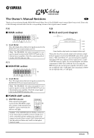
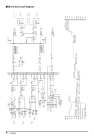
The Owner's Manual Revisions E Thank you for purchasing Yamaha EMX66M Powered Mixer. Parts of the EMX66M owner's manual have been revised. Please refer to the following revisions rather than the corresponding sections of the original owner's manual. P.10 ■ MAIN section +12 +12 +6 6 6 +3 0 0 0 6 6 -5 -12 -12 -10 125 250 500 1k 2k 4k 8k GEQ C C Level Meter This LED display shows the level of signals received at the MAIN OUT jack (input/output panel 6). Note: The SPEAKERS 1 & 2 jacks (rear panel 1) output the signals received at the MAIN OUT jack via the internal power amplifier. Check the output signal level via the LIMITER indicator (I). P.11 ■ MONITOR section +12 +12 +6 6 6 +3 0 0 0 6 6 -5 -12 -12 -10 125 250 500 1k 2k 4k 8k GEQ H H Level Meter This LED display shows the level of signals received at the MONITOR OUT jack (input/output panel 6). Note: The SPEAKERS 1 & 2 jacks (rear panel 1) output the signals received at the MONITOR OUT jack via the internal power amplifier. Check the output signal level via the LIMITER indicator (I). ■ POWER AMP section I LIMITER indicator If the output level of signals received at the SPEAKERS output jacks (output of the internal power amplifier) reaches maximum, the indicator will light. POWER AMP I LIMITER MAIN MAIN MON MAIN MAIN Caution: If the LIMITER indicator flashes continuously, the internal power amplifier section is being excessively overloaded and may malfunction. Reduce the output level at the Master control (BG) below the level that the indicator flashes only briefly on the highest transient peaks. P.28 ■ Block and Level diagram PA SPEAKERS OUT MAXIMUM OUTPUT [300W/4Ω] NOMINAL OUTPUT [60W/4Ω] +30dB +11dB +4dB +20dB +10dB 0dB Power Amplifier output section level diagram (bottom right) These plots show the nominal output and maximum output levels of signals received at the SPEAKERS jacks. If the output level is +4dB (Level Meter "0"), the internal power amplifier will deliver 60W into a 4Ω load. If the output level is +11dB (LIMITER indicator lights), the internal amplifier will deliver a maximum of 300W into a 4Ω load. If you are using the BRIDGE jack, the internal power amplifier will deliver 120W into an 8Ω load with a +4dB signal, and a maximum of 600W into an 8Ω load with a +11dB signal. 1 EMX66M
-
 1
1 -
 2
2 -
 3
3 -
 4
4 -
 5
5 -
 6
6 -
 7
7 -
 8
8 -
9
-
10
-
11
-
12
-
13
-
14
-
15
-
16
-
17
-
18
-
19
-
20
-
21
-
22
-
23
-
24
-
25
-
26
-
27
-
28
-
29
-
30
-
31
 |
 |
