Yamaha QL5 Owner's Manual - Page 11
Controls and functions, Top panel
 |
View all Yamaha QL5 manuals
Add to My Manuals
Save this manual to your list of manuals |
Page 11 highlights
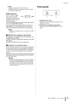
Controls and functions Top panel The top panel of the QL series is divided into the following sections. 2 3 Controls and functions 45 6 7 1 (Block A/B) 1 Channel Strip section page 12 2 SENDS ON FADER section page 12 3 Display section page 13 4 Selected Channel section page 13 5 USB connector page 15 6 USER DEFINED KEYS section page 14 7 FADER BANK section page 14 8 Master section page 14 NOTE This illustration shows the top panel of the QL5. 8 Owner's Manual 11
-
 1
1 -
2
-
3
-
4
-
5
-
 6
6 -
 7
7 -
 8
8 -
 9
9 -
 10
10 -
 11
11 -
 12
12 -
 13
13 -
 14
14 -
 15
15 -
 16
16 -
17
-
18
-
19
-
20
-
21
-
22
-
23
-
24
-
25
-
26
-
27
-
28
-
29
-
30
-
31
-
32
-
33
-
34
-
35
-
36
-
37
-
38
-
39
-
40
-
41
-
42
-
43
-
44
-
45
-
46
-
47
-
48
-
49
-
50
-
51
-
52
-
53
-
54
-
55
-
56
-
57
-
58
 |
 |

Controls and functions
Owner’s Manual
11
Controls and functions
Top panel
The top panel of the QL series is divided into the following sections.
1
Channel Strip section
page 12
2
SENDS ON FADER section
page 12
3
Display section
page 13
4
Selected Channel section
page 13
5
USB connector
page 15
6
USER DEFINED KEYS section
page 14
7
FADER BANK section
page 14
8
Master section
page 14
NOTE
This illustration shows the top panel of the QL5.
3
2
1
8
6
7
5
4
(Block A/B)