Yamaha SPX90 SPX90 Owners Manual Image - Page 18
Reverb
 |
View all Yamaha SPX90 manuals
Add to My Manuals
Save this manual to your list of manuals |
Page 18 highlights
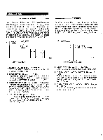
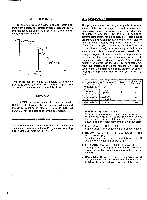
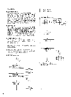
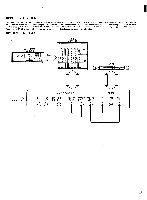
REVERB and GATE This program feeds the reverb signal through a gate circuit, making it possible to output only a segment of a longer reverb sound. Parameters provided for the reverb portion of the signal are REV TIME, HIGH, DELAY, HPF and LPF, while parameters for the gate portion are HOLD TIME, RELEASE TIME, and MIDI TRIGGER. (dB) DIRECT SIGNAL GATE ADR-NOISE GATE This program uses a gate circuit to pass or shut off the input signal in a number of ways. It can be used to pass just a short segment of a longer input signal,or it can be used to pass only signals that exceed a specific level (noise-gate type operation). It is also possible to achieve reverse gate effects in which the gain increases gradually after the gate is triggered. In addition to signal-level triggering, it is also possible to trigger the gate via a footswitch connected to the front-panel MEMORY TRIGGER jack when the FOOT TRIGGER key LED is ON. LEVEL = 100% DELAY HOLD TIME RELEASE TIME (TIME) DECAY LEVEL REVERBERATION TIME 1. REVERB TIME (R/T). Range: 0.3 - 99.0 sec 2. HIGH (High Frequency Reverb Time Ratio). Range: 0.1 - 1.0 3. DELAY. Range: 0.1 -' 50.0 msec 4. HPF (High Pass Filter). Range: 32 Hz - 1.0 kHz, THRU 5. LPF (Low Pass Filter). Range: 1.0 kHz - 11 kHz All these parameters have the same function as those of the REV programs. See page 10 for details. 6. TRIGGER LEVEL. Range: 0 - 100% Determines the strength (amplitude) of the input signal required to trigger opening of the gate. At 100%, only extremely high-level input signals will trigger the gate, while at 0% even this slightest input signal will trigger the gate. 7. HOLD TIME. Range: 1 - 30,000 msec This parameter sets the amount of time the gate is "open," allowing the reverb sound to come through. 8. RELEASE TIME. Range: 5 - 32,000 msec This parameter determines the time it takes for the gate to close completely after the HOLD TIME. 9., MIDI TRIGGER. Range: ON, OFF When ON, a KEY ON signal from an external MIDI keyboard can be used to trigger the R & G effect. ATTACK TIME. TRIGGER DECAY TIME HOLD TIME (TIME) RELEASE TIME 1. TRIGGER LEVEL. Range: 1 - 100% Determines the strength (amplitude) of the input signal required to trigger opening of the gate. At 100%, only extremely high level input signals will trigger the gate, while at 0% even the slightest input signal will trigger the gate. 2. TRIGGER DELAY. Range: -100 - -100 msec Produces a delay between the time at which the gate is triggered and that at which it actually opens. If a minus value is programmed, the input signal itself is delayed so that, effectively, the gate opens before the signal appears. 3. TRIGGER MASK. Range: 5 - 32,000 msec This parameter makes it impossible to re-trigger the gate function until the programmed time has elapsed. 4. ATTACK TIME. Range: 5 msec - 32,000 msec Determines how long it takes for the gate to open fully from the time it begins to open. 5. DECAY TIME. Range: 5 msec - 32,000 msec Determines the length of time it takes for the gate to fall to DECAY LEVEL after it is fully open. 17
-
 1
1 -
2
-
3
-
4
-
5
-
6
-
7
-
8
-
9
-
10
-
11
-
12
-
 13
13 -
 14
14 -
 15
15 -
 16
16 -
 17
17 -
 18
18 -
 19
19 -
 20
20 -
 21
21 -
 22
22 -
 23
23 -
24
-
25
-
26
-
27
-
28
-
29
-
30
-
31
-
32
-
33
-
34
 |
 |
