Yamaha SPX90 SPX90 Owners Manual Image - Page 4
Front, Panel - ii
 |
View all Yamaha SPX90 manuals
Add to My Manuals
Save this manual to your list of manuals |
Page 4 highlights
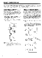
FRONT PANEL YAMAHA SPX BO 00 0 0 0 STO V 142°B1F1 II '=ILITY BYPASS 01' • Power ON/OFF Switch When the power is turned ON, the program which was selected immediately before the power was turned OFF will be re-selected. Due to the safety muting circuit, no sound will be produced by the SPX90 for a few seconds after the power is turned ON. O Input Level Control (0-10) Regulates the level of the input signal. Set the INPUT LEVEL control while watching the INPUT LEVEL meter. The seven LED meter segments should not all be continuously on when an input signal is applied, as this will result in input amplifier overload and distortion. When the INPUT LEVEL control is set to "8" on the scale, the input/output gain is 1 (unity). A setting of "10" increases gain by about 10 dB. O Input Level Meter This easy-to-read LED level meter is a visual aid to setting appropriate input levels. Generally, the best input level setting will produce continuous lighting of the lower green LED segments, while the upper red segments flash only occasionally. O Memory Number LED This LED display shows the number of the currently selected program. Memory numbers 1 through 30 contain factory-preset effects (ROM). Memory numbers 31 through 90 can be used to store edited versions of the preset effects (RAM). • LCD Program and Parameter Indicator This high-contrast Liquid Crystal Display indicates the effect name and parameter data value. O Parameter Key Selects successive effect parameters. Pressing this key sequentially calls the programmable parameters within the currently selected effect program. Once the desired parameter has been selected, the PARAMETER INCREMENT/DECREMENT keys are used to change the value of that parameter, thereby modifying the effect. The parameters available for each program are different: refer to the parameter chart on page 24. O Parameter Increment/Decrement Keys These keys are used to change the value of a selected parameter. Press the increment key (up arrow) to increase the value, or the decrement key (down arrow) to decrease the value. O Balance/Output Level Key Adjusts proportion of effect signal to direct signal. Pressing this key alternately causes the current balance and output level values to be displayed on the LCD. The Parameter Increment/Decrement keys are then used to adjust the displayed values. 3 O Store Key Stores any edited preset effect in a selected RAM memory position (31 -90). Memory Increment/Decrement Keys These keys select any desired memory number to call a specific program or store an edited program in the user memory area. The selected memory number is shown on the MEMORY NUMBER display. When a new memory number is called, the MEMORY number display will flash until either the STORE or RECALL function is activated. (1) Recall Key Press this key to recall the program that resides in the selected memory number. (IF) Utility Key Multi-purpose key accesses MIDI control functions, facilitates program title editing and sets footswitch memory control range. See pages 8 and 9 for details. ® Foot Trigger Key When this key is pressed and its LED is ON, the footswitch connected to the Memory/Trigger jack functions as a foot trigger for the GATE and FREEZE programs, rather than for memory selection. 11) Bypass Key When this key is pressed, the effect signal is shut off and only the direct signal will be output. Direct signal level is affected by the INPUT LEVEL control setting. ® Memory/Trigger Footswitch Jack Facilitates remote memory selection via optional footswitch. The range of memory locations to be recalled by the footswitch can be set with a Utility program. When the foot trigger function (above) is ON, the footswitch connected to this jack acts as a trigger footswitch rather than memory control. Use of a Yamaha FC5 Foot Controller is recommended. (15 Bypass Footswitch Jack Facilitates foot control of the BYPASS function described above. A Yamaha FC-5 Foot Controller is recommended. F C - 5
-
 1
1 -
 2
2 -
 3
3 -
 4
4 -
 5
5 -
 6
6 -
 7
7 -
 8
8 -
 9
9 -
 10
10 -
11
-
12
-
13
-
14
-
15
-
16
-
17
-
18
-
19
-
20
-
21
-
22
-
23
-
24
-
25
-
26
-
27
-
28
-
29
-
30
-
31
-
32
-
33
-
34
 |
 |
