Yamaha SPX90 SPX90 Owners Manual Image - Page 23
<=>
 |
View all Yamaha SPX90 manuals
Add to My Manuals
Save this manual to your list of manuals |
Page 23 highlights
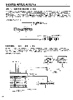
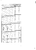
RECORDING SYSTEM In a recording system it is most desirable to have the SPX90 input and outputs available at a patch bay where they may accessed and patched into virtually any part of the system. In some cases it might be best to have the SPX90 connected directly in line between the source and the mixing console inputs, while in other situations-final mixdown, for example-the SPX90 should be patched into the mixing console's effects loop so it may be applied to the entire mix. Naturally, the SPX90 is also an ideal choice for the truly modern digital sequencer recording system, too. (SYSTEM DIAGRAM 3) MIXING CONSOLE MULTITRACK RECORDER .0 . P 0 .. 0 8888 000oop 0 0 0 O. P-- 0,- Q% 07- 0 -6 0'Q. 62. 61 Q.T. p= 05.1 P .- 0 - Q- 0 0 - P .- O * * *I i SPX90 0 it -z- am (=EPEE:Ear:. fSECTION OF PATCH BAY MIXING CONSOLE LINE LINE LINE LINE IN 1 IN 2 IN 3 IN 4 0000 EFFECT EFFECT EFFECT SEND RTN 1 RTN 2 SPX90 IN OUT OUT 22
-
 1
1 -
2
-
3
-
4
-
5
-
6
-
7
-
8
-
9
-
10
-
11
-
12
-
13
-
14
-
15
-
16
-
17
-
 18
18 -
 19
19 -
 20
20 -
 21
21 -
 22
22 -
 23
23 -
 24
24 -
 25
25 -
 26
26 -
 27
27 -
 28
28 -
29
-
30
-
31
-
32
-
33
-
34
 |
 |
