Zenith C34W23 Operating Guide - Page 11
Hook Up Cable Service CATV and VCR
 |
UPC - 044642003326
View all Zenith C34W23 manuals
Add to My Manuals
Save this manual to your list of manuals |
Page 11 highlights
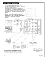
Hook Up Cable Service (CATV) and VCR Connect Cable service and a VCR to the TV Typical Cable TV Wall Jack In Cable Box output Out switch 3 4 1 Locate the Antenna/Cable In jack on the back of the VCR. 2 Connect the cable service wire that runs from the wall, according to one of the dia- grams to the right. Make any other connec- tions necessary for your setup. 3 Remove the back of the remote and put in two "AAA" batteries. Cable service with or without a cable box Typical Cable TV Wall Jack VCR Back VCR Back AV Panel In output switch 3 4 Out Audio Video Back of Remote 4 Plug in your TV. Your TV is designed to oper- ate on standard household current, 120-volt 60 Hertz AC. Do not plug it into an outlet controlled by a switch. Do not attempt to operate it on DC power. 120 V AC 60 Hz Tune both the VCR and the television to channel 3 or 4 (cable box output channel) and use the cable box to change channels. No A/V cables are included with your TV. Without A/V cable hookups, most VCRs will not play videocassettes in stereo sound. ANTENNA/ CABLE 1 206-3767 TV Back HD IN Y Pr RGB Pb DVD IN Y VIDEO 1 IN VIDEO 2 MONITOR IN OUTPUT S-VIDEO 1 S-VIDEO 2 Pr VIDEO VIDEO VIDEO Pb R AUDIO L R AUDIO L R AUDIO L R AUDIO L R AUDIO L Connect your VCR to the Video 1 or Video 2 set of input jacks PAGE 11
-
 1
1 -
2
-
3
-
4
-
5
-
 6
6 -
 7
7 -
 8
8 -
 9
9 -
 10
10 -
 11
11 -
 12
12 -
 13
13 -
 14
14 -
 15
15 -
 16
16 -
17
-
18
-
19
-
20
-
21
-
22
-
23
-
24
-
25
-
26
-
27
-
28
-
29
-
30
-
31
-
32
-
33
-
34
-
35
-
36
-
37
-
38
-
39
-
40
-
41
-
42
-
43
-
44
-
45
-
46
-
47
-
48
-
49
-
50
-
51
-
52
-
53
-
54
-
55
-
56
 |
 |
