eMachines E732 eMachines eME732 Series Service Guide - Page 56
External Modules Disassembly Process
 |
View all eMachines E732 manuals
Add to My Manuals
Save this manual to your list of manuals |
Page 56 highlights
External Modules Disassembly Process IMPORTANT:The outside housing and color may vary from the mass produced model. External Modules Disassembly Flowchart The flowchart below gives you a graphic representation on the entire disassembly sequence and instructs you on the components that need to be removed during servicing. For example, if you want to remove the mainboard, you must first remove the keyboard, then disassemble the inside assembly frame in that order. Screw List Step ODD Module Disassembly ODD Bracket Disassembly Screw M2.5*6.0-I M2.0*3.0-I Quantity 1 2 Part No. 86.A08V7.004 86.ARE07.002 46 Chapter 3
-
 1
1 -
2
-
3
-
4
-
5
-
6
-
7
-
8
-
9
-
10
-
11
-
12
-
13
-
14
-
15
-
16
-
17
-
18
-
19
-
20
-
21
-
22
-
23
-
24
-
25
-
26
-
27
-
28
-
29
-
30
-
31
-
32
-
33
-
34
-
35
-
36
-
37
-
38
-
39
-
40
-
41
-
42
-
43
-
44
-
45
-
46
-
47
-
48
-
49
-
50
-
 51
51 -
 52
52 -
 53
53 -
 54
54 -
 55
55 -
 56
56 -
 57
57 -
 58
58 -
 59
59 -
 60
60 -
 61
61 -
62
-
63
-
64
-
65
-
66
-
67
-
68
-
69
-
70
-
71
-
72
-
73
-
74
-
75
-
76
-
77
-
78
-
79
-
80
-
81
-
82
-
83
-
84
-
85
-
86
-
87
-
88
-
89
-
90
-
91
-
92
-
93
-
94
-
95
-
96
-
97
-
98
-
99
-
100
-
101
-
102
-
103
-
104
-
105
-
106
-
107
-
108
-
109
-
110
-
111
-
112
-
113
-
114
-
115
-
116
-
117
-
118
-
119
-
120
-
121
-
122
-
123
-
124
-
125
-
126
-
127
-
128
-
129
-
130
-
131
-
132
-
133
-
134
-
135
-
136
-
137
-
138
-
139
-
140
-
141
-
142
-
143
-
144
-
145
-
146
-
147
-
148
-
149
-
150
-
151
-
152
-
153
-
154
-
155
-
156
-
157
-
158
-
159
-
160
-
161
-
162
-
163
-
164
-
165
-
166
-
167
-
168
-
169
-
170
-
171
-
172
-
173
-
174
-
175
-
176
-
177
-
178
-
179
-
180
-
181
-
182
-
183
-
184
-
185
-
186
-
187
-
188
-
189
-
190
-
191
-
192
 |
 |
46
Chapter 3
External Modules Disassembly Process
IMPORTANT:
The outside housing and color may vary from the mass produced model.
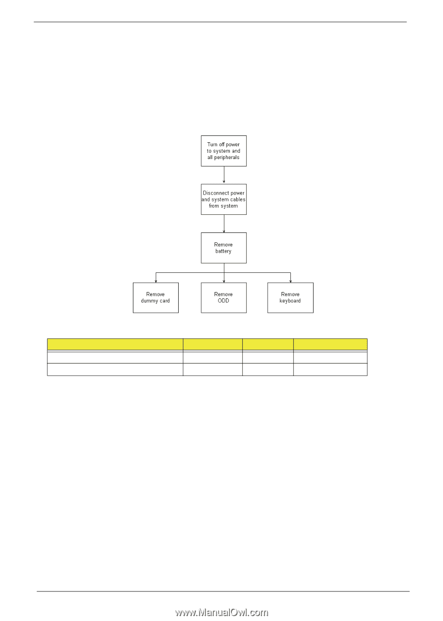
External Modules Disassembly Flowchart
The flowchart below gives you a graphic representation on the entire disassembly sequence and instructs you on
the components that need to be removed during servicing. For example, if you want to remove the mainboard, you
must first remove the keyboard, then disassemble the inside assembly frame in that order.
Screw List
Step
Screw
Quantity
Part No.
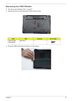
ODD Module Disassembly
M2.5*6.0-I
1
86.A08V7.004
ODD Bracket Disassembly
M2.0*3.0-I
2
86.ARE07.002