Ariens Pro Track 28 Owners Manual - Page 24
SHEAR BOLTS, HANDLEBAR HEIGHT, For Replacement
 |
View all Ariens Pro Track 28 manuals
Add to My Manuals
Save this manual to your list of manuals |
Page 24 highlights
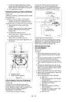
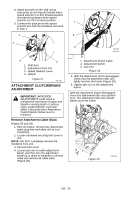
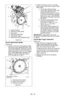
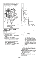
SHEAR BOLTS (Figure 22) IMPORTANT: Use only Ariens shear bolts for replacement. Use of any other type of shear bolt may result in severe damage to unit. See SERVICE PARTS on page 33. Occasionally a foreign object may enter the auger/impeller housing and jam the auger, breaking shear bolts which secure the auger to the shaft. This allows auger to turn freely on the shaft which may help prevent damage to gear drive. 2 5. Secure handlebar to frame with hardware removed in step 4 using the different hardware locations shown in Figure 23. 1 2 1 2 3 3 1 1. Auger 2. Shear Bolts Figure 22 OS7150 For Replacement: 1. Align shear bolt holes in auger with shear bolt holes in the shaft. 2. Drive shear bolt through hole (if shear bolt was broken this will drive remaining part from shaft). 3. Secure shear bolt with nut. NOTE: DO NOT overtighten the shear bolt. Tighten shear bolt to 5.8 - 12.2 lbf-ft (7.9 - 16.5 N•m). HANDLEBAR HEIGHT (Figure 23 and 24) CAUTION: AVOID INJURY. Adjust the attachment clutch, speed selector and traction clutch after changing the handlebar height. See Attachment Clutch/Brake Adjustment on page 26 and Speed Selector Adjustment on page 25. To raise or lower the handlebar: 1. Remove hair pin holding chute rod to control assembly. 2. Place unit in service position (see Service Position on page 20). 3. Remove bottom cover. 4. Remove top mounting bolts from the handlebars and adjust the handlebar up or down as needed until the handlebar mounting holes align with holes in unit frame. 4 OS7155 5 1. Upper Position 2. Lower Position 3. Handlebar 4 5 4. Upper Mounting Bolt 5. Lower Mounting Bolt Figure 23 NOTE: Insert the hair pin with the loop end on the left side of the chute rod so the control lever will cover its full range of travel. 6. Align correct chute rod holes in chute control assembly as shown in Figure 24, and then secure chute rod in position with hair pin remove in step 1. Upper Position 1 2 Lower Position 1 2 3 3 OS7160 1. Chute Control Assembly 2. Hair Pin 3. Chute Rod Figure 24 GB - 24
-
 1
1 -
2
-
3
-
4
-
5
-
6
-
7
-
8
-
9
-
10
-
11
-
12
-
13
-
14
-
15
-
16
-
17
-
18
-
 19
19 -
 20
20 -
 21
21 -
 22
22 -
 23
23 -
 24
24 -
 25
25 -
 26
26 -
 27
27 -
 28
28 -
 29
29 -
30
-
31
-
32
-
33
-
34
-
35
-
36
-
37
-
38
-
39
-
40
 |
 |
