Ariens Pro Track 28 Owners Manual - Page 26
ATTACHMENT CLUTCH/BRAKE, ADJUSTMENT, Remove Attachment Cable Slack
 |
View all Ariens Pro Track 28 manuals
Add to My Manuals
Save this manual to your list of manuals |
Page 26 highlights
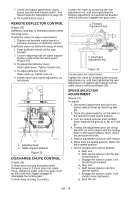
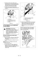
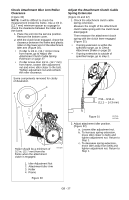
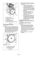
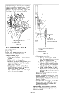
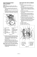
8. Adjust pivot pin on the shift rod as necessary so unit travels forward when speed selector is in first forward position and travels backward when speed selector is in first reverse position. 1 9. Connect the pivot pin to the speed selector arm with the hardware removed in step 1. 1 2 4 3 OS7185 OS7191 3 2 1. Shift Rod 2. Adjustment Pivot Pin 3. Speed Selector Lever 4. Hairpin Figure 27 OS7185 ATTACHMENT CLUTCH/BRAKE ADJUSTMENT IMPORTANT: IMPROPER ADJUSTMENT could result in unexpected movement of auger and impeller causing death or serious injury. Auger/Impeller must stop within 5 seconds when Attachment Clutch/Impeller Brake lever is released. Remove Attachment Cable Slack (Figure 28 and 29) 1. Shut off engine, remove key, disconnect spark plug wire and allow unit to cool completely. 2. Loosen hardware securing belt cover to unit. NOTE: DO NOT completely remove the hardware from unit. 3. Remove belt cover. 4. Loosen jam nut on cable adjustment barrel, and then turn the adjustment barrel up or down to lengthen or shorten cable and remove all cable slack (Figure 28). 1. Attachment Clutch Cable 2. Adjustment Barrel 3. Jam Nut Figure 28 5. With the attachment clutch disengaged, check that the attachment idler arm lightly touches the frame (Figure 29). 6. Tighten jam nut on the adjustment barrel. \ With the attachment clutch disengaged, check the attachment idler arm position here. The attachment idler arm should lightly touch the frame. Figure 29 OS7196 GB - 26
-
 1
1 -
2
-
3
-
4
-
5
-
6
-
7
-
8
-
9
-
10
-
11
-
12
-
13
-
14
-
15
-
16
-
17
-
18
-
19
-
20
-
 21
21 -
 22
22 -
 23
23 -
 24
24 -
 25
25 -
 26
26 -
 27
27 -
 28
28 -
 29
29 -
 30
30 -
 31
31 -
32
-
33
-
34
-
35
-
36
-
37
-
38
-
39
-
40
 |
 |
