Ariens Pro Track 28 Owners Manual - Page 9
Install Discharge Chute and, Discharge Chute Rod
 |
View all Ariens Pro Track 28 manuals
Add to My Manuals
Save this manual to your list of manuals |
Page 9 highlights
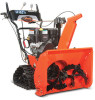
Install Discharge Chute and Discharge Chute Rod (Figure 5, 6, 7 and 8) 1. Grease underside of discharge chute ring (if not already greased). 2. Remove mounting hardware from auger housing. 3. Install discharge chute over opening in the auger housing. Finger tighten the mounting hardware removed in step 2. NOTE: Leave discharge chute pedestal loose to help install the chute rod and connect it to the control assembly. 1 7. Align the holes on the end of the chute rod with the mark on the gear assembly and slide the end without a pin through the gear assembly, through the hook on the chute lock cable and into the hex hole in the control assembly. IMPORTANT: The hook will prevent the control cable from contacting the engine or muffler guard. NOTE: After the chute rod has been inserted through the hex hole in the control assembly, placing the unit in the service position (see Service Position on page 20) will ease alignment and installation of the hair pin. 8. Secure the chute rod to the control assembly with the hair pin removed in step 6 using the end hole location as shown in Figure 7. Insert the hair pin with the loop end to the left of the chute rod so the control assembly follows a full range of travel. 3 2 OS7040 4 4 1 2 3 OS7060 1. Chute Rod 1 2. Gear Cover 3. Control Assembly 4. Hair Pin Figure 6 1. Mounting Hardware 2. Discharge Chute 3. Chute Pedestal 4. Discharge Chute Ring Figure 5 OS7045 4. Remove the cover from the gear assembly on the discharge chute. 5. Release the lock teeth on the gear assembly with your finger and rotate the ° discharge chute 90 left. 6. Remove and save the hairpin from the control assembly underneath the control panel. NOTE: Do not remove the pin installed on the chute rod. NOTE: To ensure the discharge chute follows its full range of travel, make sure the control lever is pushed all the way to the left before installing and pinning the chute rod. GB - 9 1 2 3 OS7157 1. Chute Control Assembly 2. Hair Pin 3. Chute Rod Figure 7
-
 1
1 -
2
-
3
-
 4
4 -
 5
5 -
 6
6 -
 7
7 -
 8
8 -
 9
9 -
 10
10 -
 11
11 -
 12
12 -
 13
13 -
 14
14 -
15
-
16
-
17
-
18
-
19
-
20
-
21
-
22
-
23
-
24
-
25
-
26
-
27
-
28
-
29
-
30
-
31
-
32
-
33
-
34
-
35
-
36
-
37
-
38
-
39
-
40
 |
 |
