Asus CUC2000 CUC2000 User Manual - Page 16
ASUS CUC2000 User's Manual
 |
View all Asus CUC2000 manuals
Add to My Manuals
Save this manual to your list of manuals |
Page 16 highlights
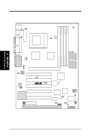
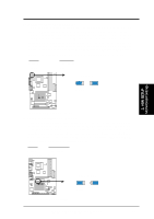
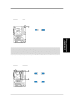
3. HARDWARE SETUP 16) IR 17) USB2, USB3 18) MIC2 19) SMB 20) PWR.LED (PANEL) 21) KEYLOCK (PANEL) 22) SPEAKER (PANEL) 23) MSG.LED (PANEL) 24) SMI (PANEL) 25) PWRSW (PANEL) 26) RESET (PANEL) 27) ATXPWR 28) JTPWR p.38 Serial and Consumer Infrared Module Connector (10-pin) p.39 USB Headers p.39 Internal Microphone Connector (3-pin MIC2) p.40 SMBus Connector (5-1 pins) p.41 System Power LED Lead (3-1 pins) p.41 Keyboard Lock Switch Lead (2 pins) p.41 System Warning Speaker Connector (4 pins) p.41 System Message LED (2 pins) p.41 System Management Interrupt Switch Lead (2 pins) p.41 ATX Power / Soft-Off Switch Lead (2 pins) p.41 Reset Switch Lead (2 pins) p.42 ATX Power Supply Connector (20 pins) p.42 Power Supply Thermal Sensor Connector (2 pins) 3. H/W SETUP Layout Contents 16 ASUS CUC2000 User's Manual
-
 1
1 -
2
-
3
-
4
-
5
-
6
-
7
-
8
-
9
-
10
-
 11
11 -
 12
12 -
 13
13 -
 14
14 -
 15
15 -
 16
16 -
 17
17 -
 18
18 -
 19
19 -
 20
20 -
 21
21 -
22
-
23
-
24
-
25
-
26
-
27
-
28
-
29
-
30
-
31
-
32
-
33
-
34
-
35
-
36
-
37
-
38
-
39
-
40
-
41
-
42
-
43
-
44
-
45
-
46
-
47
-
48
-
49
-
50
-
51
-
52
-
53
-
54
-
55
-
56
-
57
-
58
-
59
-
60
-
61
-
62
-
63
-
64
-
65
-
66
-
67
-
68
-
69
-
70
-
71
-
72
-
73
-
74
-
75
-
76
-
77
-
78
-
79
-
80
-
81
-
82
-
83
-
84
-
85
-
86
-
87
-
88
-
89
-
90
-
91
-
92
-
93
-
94
-
95
-
96
-
97
-
98
-
99
-
100
-
101
-
102
-
103
-
104
-
105
-
106
-
107
-
108
-
109
-
110
-
111
-
112
-
113
-
114
-
115
-
116
-
117
-
118
-
119
-
120
-
121
-
122
 |
 |
