Asus CUC2000 CUC2000 User Manual - Page 63
ASUS CUC2000 User's Manual, bit I/O Recovery Time
 |
View all Asus CUC2000 manuals
Add to My Manuals
Save this manual to your list of manuals |
Page 63 highlights
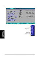
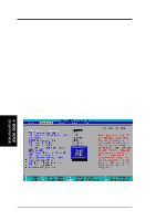
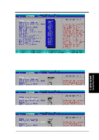
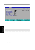
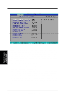
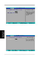
4. BIOS SETUP SDRAM MA Wait State [Normal] This controls the leadoff clocks for CPU read cycles. Leave on default setting. Configuration options: [Fast] [Normal] Graphics Window Size [64MB] This feature allows you to select the size of mapped memory for AGP graphic data. Configuration options: [4MB] [8MB] [16MB] [32MB] [64MB] [128MB] [256MB] Video Memory Cache Mode [UC] USWC (uncacheable, speculative write combining) is a new cache technology for the video memory of the processor. It can greatly improve the display speed by caching the display data. You must set this to UC (uncacheable) if your display card cannot support this feature; otherwise your system may not boot. Configuration options: [UC] [USWC] Memory Hole At 15M-16M [Disabled] This field allows you to reserve an address space for ISA expansion cards that require it. Setting the address space to a particular setting will make that memory space unavailable to the system. Expansion cards can only access memory up to 16MB. Configuration options: [Disabled] [Enabled] PCI 2.1 Support [Enabled] This function allows you to enable or disable PCI 2.1 features including passive release and delayed transaction. Configuration options: [Disabled] [Enabled] High Priority PCI Mode [Enabled] This field allows you to give PCI slot 1 a higher priority. You may want to leave on the default setting if you are using an IEEE-1394 PCI card. Configuration options: [Disabled] [Enabled] Onboard PCI IDE Enable [Both] You can select to enable the primary IDE channel, secondary IDE channel, both, or disable both channels. Configuration options: [Both] [Primary] [Secondary] [Disabled] Onboard ISA Bridge [Enabled] If you are not using any ISA cards, you may disable this field. When this field is disabled, the 8-bit and 16-bit I/O Recovery Time configurations will not be available. Configuration options: [Disabled] [Enabled] 8-bit, 16-bit I/O Recovery Time [3.5 BUSCLK] Leave on default setting. 4. BIOS SETUP Chip Configuration ASUS CUC2000 User's Manual 63
-
 1
1 -
2
-
3
-
4
-
5
-
6
-
7
-
8
-
9
-
10
-
11
-
12
-
13
-
14
-
15
-
16
-
17
-
18
-
19
-
20
-
21
-
22
-
23
-
24
-
25
-
26
-
27
-
28
-
29
-
30
-
31
-
32
-
33
-
34
-
35
-
36
-
37
-
38
-
39
-
40
-
41
-
42
-
43
-
44
-
45
-
46
-
47
-
48
-
49
-
50
-
51
-
52
-
53
-
54
-
55
-
56
-
57
-
 58
58 -
 59
59 -
 60
60 -
 61
61 -
 62
62 -
 63
63 -
 64
64 -
 65
65 -
 66
66 -
 67
67 -
 68
68 -
69
-
70
-
71
-
72
-
73
-
74
-
75
-
76
-
77
-
78
-
79
-
80
-
81
-
82
-
83
-
84
-
85
-
86
-
87
-
88
-
89
-
90
-
91
-
92
-
93
-
94
-
95
-
96
-
97
-
98
-
99
-
100
-
101
-
102
-
103
-
104
-
105
-
106
-
107
-
108
-
109
-
110
-
111
-
112
-
113
-
114
-
115
-
116
-
117
-
118
-
119
-
120
-
121
-
122
 |
 |
