Asus CUC2000 CUC2000 User Manual - Page 34
Game/MIDI Connector Gold 15-pin GAME_AUDIO optional
 |
View all Asus CUC2000 manuals
Add to My Manuals
Save this manual to your list of manuals |
Page 34 highlights
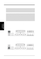
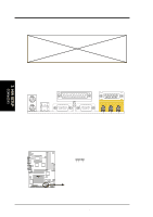
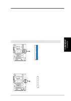
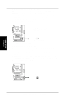
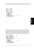
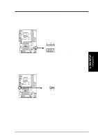
3. HARDWARE SETUP 6) Game/MIDI Connector (Gold 15-pin GAME_AUDIO) (optional) You may connect game joysticks or game pads to this connector for playing games. Connect MIDI devices for playing or editing professional audio. 3. H/W SETUP Connectors 7) Audio Port Connectors (Three 1/8" GAME_AUDIO) (optional) Line Out (lime) can be connected to headphones or preferably powered speakers. Line In (light blue) allows tape players or other audio sources to be recorded by your computer or played through the Line Out (lime). Mic (pink) allows microphones to be connected for inputting voice. Line Out Line In Mic 1/8" Stereo Audio Connectors 8) Chassis Intrusion Lead (4-1 pin CHASSIS) This requires an external detection mechanism such as a chassis intrusion monitor/sensor or microswitch. The sensor is triggered when a high level signal is sent to the Chassis Signal lead, which occurs when a panel switch or light detector is triggered. This function requires the optional ASUS CIDB chassis intrusion module to be installed (see 7. APPENDIX). If the chassis intrusion lead is not used, a jumper cap must be placed over the pins to close the circuit. CHASSIS 1 CUC2000 ® CUC2000 Chassis Open Alarm Lead Ground Chassis Signal +5Volt (Power Supply Stand By) 34 ASUS CUC2000 User's Manual
-
 1
1 -
2
-
3
-
4
-
5
-
6
-
7
-
8
-
9
-
10
-
11
-
12
-
13
-
14
-
15
-
16
-
17
-
18
-
19
-
20
-
21
-
22
-
23
-
24
-
25
-
26
-
27
-
28
-
 29
29 -
 30
30 -
 31
31 -
 32
32 -
 33
33 -
 34
34 -
 35
35 -
 36
36 -
 37
37 -
 38
38 -
 39
39 -
40
-
41
-
42
-
43
-
44
-
45
-
46
-
47
-
48
-
49
-
50
-
51
-
52
-
53
-
54
-
55
-
56
-
57
-
58
-
59
-
60
-
61
-
62
-
63
-
64
-
65
-
66
-
67
-
68
-
69
-
70
-
71
-
72
-
73
-
74
-
75
-
76
-
77
-
78
-
79
-
80
-
81
-
82
-
83
-
84
-
85
-
86
-
87
-
88
-
89
-
90
-
91
-
92
-
93
-
94
-
95
-
96
-
97
-
98
-
99
-
100
-
101
-
102
-
103
-
104
-
105
-
106
-
107
-
108
-
109
-
110
-
111
-
112
-
113
-
114
-
115
-
116
-
117
-
118
-
119
-
120
-
121
-
122
 |
 |
