Asus K8N-DL User Guide
Asus K8N-DL Manual
 |
View all Asus K8N-DL manuals
Add to My Manuals
Save this manual to your list of manuals |
Asus K8N-DL manual content summary:
- Asus K8N-DL | User Guide - Page 1
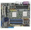
K8N-DL Motherboard - Asus K8N-DL | User Guide - Page 2
Product warranty or service will not be extended if: (1) the product is repaired, modified or altered, unless such repair, modification of alteration is authorized in writing by ASUS; or (2) the serial number of the product is defaced or missing. ASUS PROVIDES THIS MANUAL "AS IS" WITHOUT WARRANTY - Asus K8N-DL | User Guide - Page 3
Typography ix K8N-DL specifications summary x Chapter 1: Product introduction 1.1 Welcome 1-1 1.2 Package contents 1-1 1.3 Special features 1-2 1.3.1 Product highlights 1-2 1.3.2 Innovative ASUS features 1-4 Chapter 2: Hardware information 2.1 Before you proceed 2-1 2.2 Motherboard overview - Asus K8N-DL | User Guide - Page 4
CrashFree BIOS 2 utility 4-5 4.1.5 ASUS EZ Flash utility 4-7 4.1.6 ASUS Update utility 4-8 4.2 BIOS setup program 4-11 4.2.1 BIOS menu screen 4-12 4.2.2 Menu bar 4-12 4.2.3 Legend bar 4-13 4.2.4 Menu items 4-13 4.2.5 Sub-menu items 4-13 4.2.6 Configuration fields 4-13 4.2.7 Pop-up window - Asus K8N-DL | User Guide - Page 5
4.4.1 CPU Configuration 4-20 4.4.2 Memory Configuration 4-21 4.4.3 Chipset 4-23 4.4.4 Onboard Device 4-26 4.4.5 PCIPnP 4-30 4.4.6 USB Configuration 4-32 4.5 Power menu Configuration 4-41 4.6.5 Security 4-43 4.7 Exit menu 4-45 Appendix: Reference information A.1 K8N-DL block diagram A-1 v - Asus K8N-DL | User Guide - Page 6
reasonable protection against harmful interference in a residential installation. This equipment generates, uses and can radiate radio frequency energy and, if not installed and used in accordance with manufacturer's instructions, may cause harmful interference to radio communications. However - Asus K8N-DL | User Guide - Page 7
are using, contact your local power company. • If the power supply is broken, do not try to fix it by yourself. Contact a qualified service technician or your retailer. Operation safety • Before installing the motherboard and adding devices on it, carefully read all the manuals that came with the - Asus K8N-DL | User Guide - Page 8
guide This user guide contains the information you need when installing and configuring the motherboard. How this guide is organized This manual contains the following parts: • Chapter 1: Product introduction This chapter describes the features of the motherboard and the new technologies it supports - Asus K8N-DL | User Guide - Page 9
manual. D A N G E R / W A R N I N G : Information to prevent injury to yourself when trying to complete a task. C A U T I O N : Information to prevent damage to the components when trying to complete a task. I M P O R T A N T : Instructions shown, then supply the required item or value enclosed in - Asus K8N-DL | User Guide - Page 10
K8N-DL specifications summary CPU Chipset System Bus Memory Expansion slots Storage Dual Socket 940 for AMD Opteron™ 64 processors Supports AMD 64 architecture that enables simultaneous 32-bit and 64-bit computing NVIDIA® CK8-04 Professional 1600/2000 MT per second Dual-channel memory architecture - Asus K8N-DL | User Guide - Page 11
audio ports 4 Mb Flash ROM, Phoenix-Award BIOS, PnP, DMI2.0, WfM2.0, SM BIOS 2.3 ATX power supply (with 24-pin and 8-pin 12 V plugs) ATX 12 V 2.0 compliant ATX form factor: 12 in x 10.5 in (30.5 cm x 26.7 cm) Device drivers Silicon Image® RAID Utility NVIDIA® RAID utility ASUS Live Update utility - Asus K8N-DL | User Guide - Page 12
xii - Asus K8N-DL | User Guide - Page 13
This chapter describes the motherboard features and the new technologies it supports. 1Product introduction - Asus K8N-DL | User Guide - Page 14
Chapter summary 1.1 Welcome 1-1 1.2 Package contents 1-1 1.3 Special features 1-2 ASUS K8N-DL - Asus K8N-DL | User Guide - Page 15
Application CD Documentation ASUS K8N-DL motherboard IEEE1394 (1 port) module USB 2.0 + GAME port module 4 x Serial ATA signal cables (dual plugs) 4 x Serial ATA power cables (dual plugs) 2 x 40-conductor IDE cable Floppy disk drive cable I/O shield ASUS motherboard support CD User guide If any of - Asus K8N-DL | User Guide - Page 16
1.3 Special features 1.3.1 Product highlights Latest processor technology The motherboard comes with dual 940-pin sockets for the AMD Opteron™ 64 processors. The processors are based on AMD's 64-bit and 32-bit architecture, which represents the landmark introduction of the industry's first x86-64 - Asus K8N-DL | User Guide - Page 17
The motherboard implements the Universal Serial Bus (USB) 2.0 specification, dramatically increasing the connection speed from the 12 Mbps bandwidth on USB 1.1 to a fast 480 Mbps on USB 2.0. USB 2.0 is backward compatible with USB 1.1. See pages 2-21 and 2-26 for details. ASUS K8N-DL 1-3 - Asus K8N-DL | User Guide - Page 18
allows you to restore the original BIOS data from the support CD in case when the BIOS codes and data are corrupted. This protection eliminates the need to buy a replacement ROM chip. See details on page 4-5. ASUS MyLogo2™ This new feature present in the motherboard allows you to personalize and add - Asus K8N-DL | User Guide - Page 19
This chapter lists the hardware setup procedures that you have to perform when installing system components. It includes description of the jumpers and connectors on the motherboard. 2 Hardware information - Asus K8N-DL | User Guide - Page 20
Chapter summary 2.1 Before you proceed 2-1 2.2 Motherboard overview 2-3 2.3 Central Processing Unit (CPU 2-7 2.4 System memory 2-11 2.5 Expansion slots 2-14 2.6 Jumpers 2-17 2.7 Connectors 2-20 ASUS K8N-DL - Asus K8N-DL | User Guide - Page 21
the system is ON, in sleep mode, or in soft-off mode. This is a reminder that you should shut down the system and unplug the power cable before removing or plugging in any motherboard component. SB_PWR1 ® K8N-DL K8N-DL Standby power LED ON Standby Power OFF Powered Off ASUS K8N-DL 2-1 - Asus K8N-DL | User Guide - Page 22
2. CPU warning LED The CPU warning LED lights up to indicate that CPU1 has not been installed properly. If this LED stays off, this means that CPU has been installed properly. CPU_WARN1 ® K8N-DL K8N-DL CPU warning LED ON CPU1 install fail OFF CPU install well 2-2 Chapter 2: Hardware - Asus K8N-DL | User Guide - Page 23
as indicated in the image below. 2.2.2 Screw holes Place ten (10) screws into the holes indicated by circles to secure the motherboard to the chassis. Do not overtighten the screws! Doing so can damage the motherboard. Place this side towards the rear of the chassis ® K8N-DL ASUS K8N-DL 2-3 - Asus K8N-DL | User Guide - Page 24
2.2.3 Motherboard layout PARALLEL PORT DDR DIMM_B3 (72 bit, 184-pin module) DDR DIMM_A3 (72 bit, 184-pin module) SOCKET 940 PS/2KBMS T: Mouse B: Keyboard SPDIF_O1 CMOS Power 4Mb BIOS SATA3 SATA4 LAN_EN1 TSB43AB22A 1394_EN1 REAR_FAN2 REAR_FAN1 IEEE1394_1 SB_PWR1 PCI_E2 ® K8N-DL NVIDIA - Asus K8N-DL | User Guide - Page 25
Sockets 1. CPU sockets 2. DDR DIMM sockets 3. PCI/PCI Express slots Jumpers 1. Clear RTC RAM (CLRTC1) 2. Keyboard power (3-pin KBPWR1) 3. 1394 controller setting (3-pin 1394_EN1) 4. Gigabit LAN controller setting (3-pin LAN1_EN1) 5. RAID 2-20 2-21 2-21 2-21 2-21 2-21 2-21 2-21 2-21 ASUS K8N-DL 2-5 - Asus K8N-DL | User Guide - Page 26
SATA4) 2-23 4. Serial ATA RAID connectors (7-pin SATA_RAID1, SATA_RAID2, SATA_RAID3, SATA_RAID4) 2-24 5. CPU, front, and rear fan 26 9. ATX power connectors (24-pin EATXPWR1, 8-pin ATX12V1) 2-27 10. GAME/MIDI port connector (16-1 pin GAME1) 2-28 11. Internal audio connectors (4-pin - Asus K8N-DL | User Guide - Page 27
CPU To install a CPU: 1. Locate the CPU socket on the motherboard. CPU2 CPU1 ® K8N-DL K8N-DL CPU Socket 940 • Before installing the CPU, make sure that the socket box is facing towards you and the load lever is on your left. • If installing only one CPU, use the CPU socket marked CPU1. ASUS K8N-DL - Asus K8N-DL | User Guide - Page 28
fits in place. Triangle mark Notched corner The CPU fits only in one correct orientation. DO NOT force the CPU into the socket to prevent bending the pins and damaging the CPU! 5. When the CPU is in place, push down the socket lever to secure the CPU. The lever clicks on the side tab to indicate - Asus K8N-DL | User Guide - Page 29
Module Base Retention bracket Retention bracket lock Your boxed CPU heatsink and fan assembly should come with installation instructions for the CPU, heatsink, and the retention mechanism. If the instructions in this section do not match the CPU documentation, follow the latter. ASUS K8N-DL 2-9 - Asus K8N-DL | User Guide - Page 30
2. Attach one end of the retention bracket to the retention module base. 3. Align the other end of the retention bracket (near the retention bracket lock) to the retention module base. A clicking sound denotes that the retention bracket is in place. Make sure that the fan and heatsink assembly - Asus K8N-DL | User Guide - Page 31
Dual Inline Memory Modules (DIMM) sockets. The following figure illustrates the location of the sockets: DIMM_A3 DIMM_B3 DIMM_B2 80 Pins DIMM_A2 DIMM_B1 DIMM_A1 104 Pins ® K8N-DL K8N-DL 184-pin DDR DIMM sockets For CPU 1 Channel A Channel B For CPU 2 Channel A Channel B ASUS K8N-DL Sockets - Asus K8N-DL | User Guide - Page 32
DDR DIMMs into the DIMM sockets using the memory configurations in this section. • For dual-channel configuration, the total size of memory module(s) installed per channel must be the same for better performance. Single CPU: DIMM_A1+DIMM_A2=DIMM_B1+DIMM_B2 Dual CPU: DIMM_A1+DIMM_A2=DIMM_B1+DIMM_B2 - Asus K8N-DL | User Guide - Page 33
Installing a DIMM Make sure to unplug the power supply before adding or removing DIMMs or other system components. Failure to do so may cause severe damage to both the motherboard and the components. 1. Unlock a DIMM socket by pressing the retaining clips outward. 2. Align a DIMM on the socket - Asus K8N-DL | User Guide - Page 34
expansion cards that they support. Make sure to unplug the power cord before adding or removing expansion cards. Failure to do so may cause you physical injury and damage motherboard components. 2.5.1 Installing an expansion card To install an expansion card: 1. Before installing the expansion card - Asus K8N-DL | User Guide - Page 35
CMOS/Real Time Clock IRQ holder for PCI steering* IRQ holder for PCI steering* IRQ holder for PCI steering* PS/2 Compatible Mouse Port* Numeric Data Processor Primary IDE Channel Secondary IDE Channel * These IRQs are usually available for ISA or PCI devices. ASUS K8N-DL 2-15 - Asus K8N-DL | User Guide - Page 36
card, SCSI card, USB card, and other cards that comply with PCI specifications. The figure shows a LAN card installed on a PCI slot. 2.5.5 PCI Express x16 slot This motherboard supports one PCI Express x16 graphics card that complies with the PCI Express specifications. The figure shows a graphics - Asus K8N-DL | User Guide - Page 37
Clear CMOS You do not need to clear the RTC when the system hangs due to overclocking. For system failure due to overclocking, use the C.P.R. (CPU Parameter Recall) feature. Shut down and reboot the system so the BIOS can automatically reset parameter settings to default values. ASUS K8N-DL 2-17 - Asus K8N-DL | User Guide - Page 38
default is the Space Bar). This feature requires an ATX power supply that can supply at least 1A on the +5VSB lead, and a corresponding setting in the BIOS. KBPWR1 1 2 +5V (Default) 2 3 +5VSB ® K8N-DL K8N-DL Keyboard power setting 3 . 1394 controller setting (3-pin 1394_EN1) This jumper allows - Asus K8N-DL | User Guide - Page 39
the onboard Broadcom® BCM5751 Gigabit LAN1 controller. Set to pins 1-2 to activate the Gigabit LAN feature. ® K8N-DL LAN1_EN1 2 1 Enable (Default) 3 2 Disable K8N-DL CPU LAN1_EN setting 5 . RAID controller setting (3-pin RAID_EN1) This jumper allows you to enable or disable the onboard Silicon - Asus K8N-DL | User Guide - Page 40
4 a p o r t . This 6-pin IEEE 1394 port provides high-speed connectivity for audio/video devices, storage peripherals, PCs, or portable devices. 4 . L A N 1 ( R J - 4 5 ) p o r t . Supported by the BROADCOM® BCM5751 Gigabit LAN controller, this port allows Gigabit connection to a Local Area Network - Asus K8N-DL | User Guide - Page 41
an external audio output device via an optical S/PDIF cable. 1 5 . C o a x i a l S / P D I F O u t p o r t . This port connects an external audio output device via a coaxial S/PDIF cable. 1 6 . P S / 2 k e y b o a r d p o r t ( p u r p l e ) . This port is for a PS/2 keyboard. ASUS K8N-DL 2-21 - Asus K8N-DL | User Guide - Page 42
cable to PIN 1. K8N-DL Floppy disk drive connector 2 . IDE connectors (40-1 pin PRI_IDE1, SEC_IDE1) These connectors are for Ultra DMA 133/100/66 signal cables. The Ultra DMA 133/100/66 signal cable has three connectors: a blue connector for the primary IDE connector on the motherboard, a black - Asus K8N-DL | User Guide - Page 43
RSATA_TXP4 RSATA_TXN4 GND RSATA_RXN4 RSATA_RXP4 GND Important notes on Serial ATA • The actual data transfer rate depends on the speed of Serial ATA hard disks installed. • See Appendix for instructions on how to install the Serial ATA extension module. ASUS K8N-DL 2-23 - Asus K8N-DL | User Guide - Page 44
SATA_RAID4 K8N-DL SATA RAID connectors • Before creating a RAID configuration, make sure that you have connected the Serial ATA cables to these connectors and have installed the Serial ATA hard disks drives; otherwise, you cannot enter the Silicon Image RAID utility and Serial ATA BIOS setup - Asus K8N-DL | User Guide - Page 45
the motherboard components. These are not jumpers! DO NOT place jumper caps on the fan connectors! • The ASUS Smart Q-Fan function is supported using the CPU fans (CPU_FAN1, CPU_FAN2) connectors. • The chipset fan is synchronized with the CPU fans. CPU_FAN2 CPU_FAN1 REAR_FAN1 REAR_FAN2 ® K8N-DL - Asus K8N-DL | User Guide - Page 46
connector, then install the module to a slot opening at the back of the system chassis. +12V TPB0+ GND TPA0+ ® K8N-DL 1 IE1394_1 K8N-DL IEEE-1394 connector GND +12V TPB0GND TPA0- Never connect a U S B c a b l e to the IEEE 1394 connectors. Doing so will damage the motherboard! 2-26 Chapter - Asus K8N-DL | User Guide - Page 47
Ground PSON# Ground Ground Ground -5 Volts +5 Volts +5 Volts +5 Volts Ground K8N-DL ATX Power connectors +3 Volts +3 Volts Ground +5 Volts Ground +5 Volts Ground Power OK +5V Standby +12 Volts +12 Volts +3 Volts 12V 12V For Power Supply with 20-pin Power Connector 12V 12V ASUS K8N-DL 2-27 - Asus K8N-DL | User Guide - Page 48
this connector, then install the module to a slot opening at the back of the system chassis. The GAME/MIDI port connects a joystick or game pad for playing games, and MIDI devices for playing or editing audio files. +5V J1B2 J1CY GND GND J1CX J1B1 +5V ® K8N-DL K8N-DL Game connector GAME1 MIDI_IN - Asus K8N-DL | User Guide - Page 49
that supports legacy AC '97 audio standard. Connect one end of the front panel audio I/O module cable to this connector. +5VSB_MB Chassis Signal GND ® K8N-DL FP_AUDIO1 MIC2 MICPWR Line out_R NC Line out_L AGND +5VA BLINE_OUT_R BLINE_OUT_L K8N-DL Front panel audio connector ASUS K8N-DL 2-29 - Asus K8N-DL | User Guide - Page 50
connector supports several chassis-mounted functions. MLED PLED SPKO PLED+ PLEDMLED+ MLED+5V Ground Ground Speaker PANEL1 HD_LED+ HD_LED- PWR GND Reset GND ® K8N-DL HD_LED RESET PWRSW * Requires an ATX power supply. K8N-DL System panel connector The system panel connector is color-coded - Asus K8N-DL | User Guide - Page 51
This chapter describes the power up Powerin3g up sequence, the vocal POST messages, and ways of shutting down the system. - Asus K8N-DL | User Guide - Page 52
Chapter summary 3.1 Starting up for the first time 3-1 3.2 Powering off the computer 3-2 3.3 ASUS POST Reporter 3-3 ASUS K8N-DL - Asus K8N-DL | User Guide - Page 53
30 seconds from the time you turned on the power, the system may have failed a power-on test. Check the jumper settings and connections or call your retailer for assistance. 7. At power on, hold down the key to enter the BIOS Setup. Follow the instructions in Chapter 4. ASUS K8N-DL 3-1 - Asus K8N-DL | User Guide - Page 54
down. If you are using Windows® XP: 1. Click the S t a r t button then select T u r n O f f C o m p u t e r . 2. Click the T u r n O f f button to shut down the computer. 3. The power supply should turn off after Windows® shuts down. 3.2.2 Using the dual function power switch While the system is ON - Asus K8N-DL | User Guide - Page 55
processor to the CPU socket. See section "2.3 Central Processing Unit (CPU)" for details. • Check the CPU if properly installed. • Call ASUS technical support for assistance. See the ASUS contact information on the inside front cover of this user guide. • Install supported DDR DIMMs into the memory - Asus K8N-DL | User Guide - Page 56
system. • Make sure that your CPU fan supports the fan speed detection function. • Check your power supply and make sure it is not defective. • Call ASUS technical support for assistance. See the "ASUS contact information" on the inside front cover of this user guide. • No action required You can - Asus K8N-DL | User Guide - Page 57
the vocal POST messages. You can install this application from the support CD. To avoid conflicts, do not run the Winbond Voice Editor while running the ASUS PC Probe application. Launching the Voice Editor , then click the Play button. The default language setting is English. ASUS K8N-DL 3-5 - Asus K8N-DL | User Guide - Page 58
d button from the Voice Editor main window. A window with the available languages appears. 2. language you selected appear on the Voice Editor main window. Not all events on some languages have a window to update the EEPROM. 4. Click Y e s to confirm. The next time you boot your computer, the ASUS - Asus K8N-DL | User Guide - Page 59
POST messages if your language is not supported or if you wish to to replace the pre-installed wave files. To customize your POST messages d button to display the A d d W a v e F i l e window. 5. Copy the wave files that you recorded to the database, then close the window when done. ASUS K8N-DL 3-7 - Asus K8N-DL | User Guide - Page 60
i t e button to compress the file and copy into the EEPROM. 13. Click Y e s on the confirmation window that appears. If you receive an error message telling you that the files exceed the total allowable size, do any or events like FDD Detection, IDE HDD Detection, etc. 3-8 Chapter 3: Powering up - Asus K8N-DL | User Guide - Page 61
This chapter tells how to change the system settings through the BIOS Setup menus. Detailed descriptions of the BIOS parameters are also provided. 4 BIOS setup - Asus K8N-DL | User Guide - Page 62
Chapter summary 4 4.1 Managing and updating your BIOS 4-1 4.2 BIOS setup program 4-11 4.3 Main menu 4-15 4.4 Advanced menu 4-20 4.5 Power menu 4-33 4.6 Boot menu 4-39 4.7 Exit menu 4-45 ASUS K8N-DL - Asus K8N-DL | User Guide - Page 63
in Windows® environment.) Refer to the corresponding sections for details on these utilities. Save a copy of the original motherboard BIOS file to a bootable floppy disk in case you need to restore the BIOS in the future. Copy the original motherboard BIOS using the ASUS Update or AwardBIOS Flash - Asus K8N-DL | User Guide - Page 64
or the latest motherboard BIOS file to the bootable floppy disk. 4.1.2 Updating the BIOS The Basic Input/Output System (BIOS) can be updated using the AwardBIOS Flash Utility. Follow these instructions to update the BIOS using this utility. 1. Download the latest BIOS file from the ASUS web site - Asus K8N-DL | User Guide - Page 65
Flash Type - SST 49LF004A/B /3.3V flashed the BIOS file. File Name to Program: 1001.bin Remove the floppy disk then press to Flashing Complete Press to Continue restart the system. 111122223333 Write OK 111122223333 No Update 111122223333 Write Fail F1 Reset ASUS K8N-DL 4-3 - Asus K8N-DL | User Guide - Page 66
Please Wait! 4. The utility saves the current BIOS file to the floppy disk, then returns to the BIOS flashing process. AwardBIOS Flash Utility for ASUS V1.01 (C) Phoenix Technologies Ltd. All Rights Reserved For NF-KC804-K8N-DL-00 DATE: 02/01/2005 Flash Type - SST 49LF004A/B /3.3V File Name to - Asus K8N-DL | User Guide - Page 67
, Inc. BIOS ROM checksum error Detecting IDE ATAPI device... Found CDROM, try to Boot from it... Pass DO NOT shut down or reset the system while updating the BIOS! Doing so can cause system boot failure! 4. Restart the system after the utility completes the updating process. ASUS K8N-DL 4-5 - Asus K8N-DL | User Guide - Page 68
updating the BIOS! Doing so can cause system boot failure! 4. Restart the system after the utility completes the updating process. The recovered BIOS may not be the latest BIOS version for this motherboard. Visit the ASUS website (www.asus.com) to download the latest BIOS file. 4-6 Chapter 4: BIOS - Asus K8N-DL | User Guide - Page 69
chip so it is accessible by pressing + during the Power-On Self Tests (POST). To update the BIOS using EZ Flash: 1. Visit the ASUS website (www.asus.com) to download the latest BIOS file for the motherboard. 2. Save the BIOS file to a floppy disk, then restart the system. 3. Press - Asus K8N-DL | User Guide - Page 70
the BIOS version information. This utility is available in the support CD that comes with the motherboard package. ASUS Update requires an Internet connection either through a network or an Internet Service Provider (ISP). Installing ASUS Update To install ASUS Update: 1. Place the support CD in - Asus K8N-DL | User Guide - Page 71
S U p d a t e. The ASUS Update main window appears. 2. Select U p d a t e B I O S f r o m 3. Select the ASUS FTP site t h e I n t e r n e t option from the nearest you to avoid network drop-down menu, then click traffic, or click A u t o S e l e c t. N e x t. Click N e x t. ASUS K8N-DL 4-9 - Asus K8N-DL | User Guide - Page 72
to download. Click Next. 5. Follow the screen instructions to complete the update process. The ASUS Update utility is capable of updating itself through the Internet. Always update the utility to avail all its features. Updating the BIOS through a BIOS file To update the BIOS through a BIOS file - Asus K8N-DL | User Guide - Page 73
under the Exit Menu. See section "4.7 Exit Menu." • The BIOS setup screens shown in this section are for reference purposes only, and may not exactly match what you see on your screen. • Visit the ASUS website (www.asus.com) to download the latest BIOS file for this motherboard. ASUS K8N-DL 4-11 - Asus K8N-DL | User Guide - Page 74
screen Menu items Menu bar Configuration fields General help Phoenix-Award BIOS CMOS Setup Utility Main Advanced Power Boot Exit System Time System Date Legacy Diskette A Floppy 3 Mode Support Primary IDE Master Primary IDE Slave Secondary IDE Master Secondary IDE Slave Third IDE Master Fourth - Asus K8N-DL | User Guide - Page 75
Help screen Loads setup default values Exits the BIOS setup or returns to the main menu from a sub-menu Left or M a i n shows the Main menu items. The other items (Advanced, Power, Boot, and Exit) on the menu bar have their respective menu items. Pop-up window." ASUS K8N-DL 4-13 - Asus K8N-DL | User Guide - Page 76
window with the configuration options for that item. Phoenix-Award BIOS CMOS Setup Utility Main Advanced Power Boot Exit System Time System Date 15 : 30 : 36 Wed, Feb 2 2005 Legacy Diskette A Floppy 3 Mode Support 5 Master [None] Base Memory Extended Memory Total Memory 256K ↑↓ :Move ENT2E6R1: - Asus K8N-DL | User Guide - Page 77
floppy disk. This is required to support Japanese standard floppy drives. Configuration options: [Disabled] [Drive A] 4.3.5 Base/Extended/Total Memory [xxxxxxK] The base memory, extended memory, and the total memory values are auto-detected. These fields are not user-configurable. ASUS K8N-DL 4-15 - Asus K8N-DL | User Guide - Page 78
improved transfer speeds and data integrity for supported IDE devices. Configuration options: [Disabled] BIOS may detect incorrect parameters. Select [Manual] to manually enter the IDE hard disk drive parameters. Refer to the next section "Manually detecting an IDE drive." If no drive is installed - Asus K8N-DL | User Guide - Page 79
make sure you have the correct configuration information supplied by the drive manufacturer. Incorrect settings may cause the system to fail to recognize the installed hard disk. To enter the number of cylinder disk capacity. Cylinder Shows the number of the hard disk cylinders. ASUS K8N-DL 4-17 - Asus K8N-DL | User Guide - Page 80
Zone Displays the drive's maximum usable capacity as calculated by the BIOS based on the drive information that you entered. Sector Shows the Monitoring, Analysis, and Reporting Technology (S.M.A.R.T) status if the hard disk supports this feature. Otherwise, this item is grayed out and show the - Asus K8N-DL | User Guide - Page 81
which are not discussed in this section. Main Phoenix-Award BIOS CMOS Setup Utility Primary IDE Master Extended IDE Drive Access When set to [Auto], allows automatic selection of the extended IDE drive installed, if any. Set this item to [None] if there is no item descriptions. ASUS K8N-DL 4-19 - Asus K8N-DL | User Guide - Page 82
of the Advanced menu items. Incorrect field values can cause the system to malfunction. Phoenix-Award BIOS CMOS Setup Utility Main Advanced Power Boot Exit CPU Configuration Memory Configuration Chipset Onboard Device PCIPnP USB Configuration Select Menu Item Specific Help Press Enter to set F1 - Asus K8N-DL | User Guide - Page 83
T i m e, R A S # t o C A S # D e l a y, and R o w P r e c h a r g e T i m e become configurable only when the Timing Mode item is set to [Manual]. Memclock Index Value (Mhz) [200MHz] Allows selection of the DRAM frequency. Configuration options: [100Mhz] [133Mhz] [166Mhz] [200Mhz] ASUS K8N-DL 4-21 - Asus K8N-DL | User Guide - Page 84
Enabled] Enables or disables ECC check/correct mode. Configuration options: [Disabled] [Enabled] ECC Memory Interlock [At Least One] Allows selection for DIMMs that are ECC-compliant. Configuration options: is encountered. Configuration options: [Disabled] [Enabled] 4-22 Chapter 4: BIOS setup - Asus K8N-DL | User Guide - Page 85
Transport Width Errata 94 Enhanced System BIOS Cacheable Spread Spectrum SATA Spread Spectrum PCIE Spread Spectrum SSE/SSE2 Instructions Init Display First IDE DMA Transfer ] [Enabled] [Enabled] [Enabled] [Enabled] Select Menu Item Specific Help Disable/Enable OnChip IDE Channel0. ASUS K8N-DL 4-23 - Asus K8N-DL | User Guide - Page 86
of the system BIOS. Configuration options: [Disabled] [Enabled] Spread Spectrum [Enabled] Enables or disables the CPU spread spectrum. Configuration SSE/SSE2 Instructions [Enabled] Enables or disables the SSE instructions. Configuration options: [Disabled] [Enabled] 4-24 Chapter 4: BIOS setup - Asus K8N-DL | User Guide - Page 87
options: [Disabled] [Enabled] SATA2 DMA Transfer [Enabled] Enables or disables the switch to support SATA2 DMA transfer. Configuration options: [Disabled] [Enabled] IDE Prefetch Mode [Enabled] Enables or disables the IDE Prefetch mode. Configuration options: [Disabled] [Enabled] ASUS K8N-DL 4-25 - Asus K8N-DL | User Guide - Page 88
Report System Booting Onboard Silicon SATALink Onboard 1394 Onboard Broadcom 5751 LAN Onboard LAN Boot ROM Onboard AC97 Audio NVRAID Configuration Super I/O Device [Enabled] [Disabled] [Disabled] the onboard 1394 controller. Configuration options: [Disabled] [Enabled] 4-26 Chapter 4: BIOS setup - Asus K8N-DL | User Guide - Page 89
When enabled, allows you to use the device/s for creating a RAID set. Configuration options: [Disabled] [Enabled] First/Second/Third/Fourth SATA Master RAID [Disabled] When enabled, allows you to use the device/s for creating a RAID set. Configuration options: [Disabled] [Enabled] ASUS K8N-DL 4-27 - Asus K8N-DL | User Guide - Page 90
function items. Select the items that you wish to enable to create a RAID set. NVRAID Configuration Serial Port1 Address Onboard Parallel Port Parallel Port Mode EPP P a r a l l e l P o r t M o d e is set to [ECP] or [ECP+EPP]. Configuration options: [EPP1.9] [EPP1.7] 4-28 Chapter 4: BIOS setup - Asus K8N-DL | User Guide - Page 91
the MIDI port address. Configuration options: [Disabled] [330] [300] [290] Midi Port IRQ [10] Allows you to select the MIDI port IRQ. Configuration options: [5] [10] ASUS K8N-DL 4-29 - Asus K8N-DL | User Guide - Page 92
IRQ DMA and memory base address fields, since BIOS automatically assigns them. Resources Controlled By [Auto] Allows automatic or manual assignments of IRQ may not show colors properly. Setting this field to [Enabled] corrects this problem. If you are using a standard VGA card, leave this field to - Asus K8N-DL | User Guide - Page 93
c e s and assign the interrupts depending on the type of installed PCI devices. Memory Configuration Resources Controlled By IRQ Resources [Manual] PCI/VGA Pallete Snoop [Disabled] ** PCI Express relative items ** ISA devices. Configuration options: [PCI Device] [Reserved] ASUS K8N-DL 4-31 - Asus K8N-DL | User Guide - Page 94
[Enabled] allows the built-in high speed USB support in the BIOS to turn on automatically when you install high speed USB devices. Configuration options: [Disabled] [Enabled] USB Legacy Mode Support [Enabled] Allows you to enable or disable support for the legacy USB devices. Configuration options - Asus K8N-DL | User Guide - Page 95
Select Menu Item Specific Help Enable/Disable ACPI support for Operating System. ACPI APIC Support [Enabled] Allows you to enable or disable Advanced Configuration and Power Interface (ACPI) state to be used for system suspend. Configuration options: [S1(POS)] [S3(STR)] [S1&S3] ASUS K8N-DL 4-33 - Asus K8N-DL | User Guide - Page 96
options: [Disabled] [1 Min] [2 Min]... [15 Min] Video Off Method [DPMS Support] Allows you to select the video off method. The Display Power Management System (DPMS) feature allows the BIOS to control the video display card if it supports DPMS. [Blank Screen] only blanks the screen. Use this for - Asus K8N-DL | User Guide - Page 97
goes into whatever was the system state (on or off) before the power interruption. Configuration options: [Power Off] [Power On] [Last State] Power On By PCI Devices [Disabled] Allows you to enable or disable press . 6. Key-in a value (Min=0, Max=59), then press . ASUS K8N-DL 4-35 - Asus K8N-DL | User Guide - Page 98
the PS/2 mouse to turn on the system. This feature requires an ATX power supply that provides at least 1A on the +5VSB lead. Configuration options: [ Smart Q-Fan Configuration System Temperature CPU1 Temperature CPU2 Temperature CPU Fan1 speed CPU Fan2 speed Front Fan1 speed Front Fan2 speed Rear - Asus K8N-DL | User Guide - Page 99
[1.70V] [1.80V] CPU1 Voltage Control CPU2 Voltage Control Allow you to select the CPU voltages. Configuration options: [Default VID or plus 100mV] [Default VID] Hyper Transport Voltage Allow you to adjust the chipset voltage. Configuration options: [1.20V] [1.25V] [1.30V] [1.35V] ASUS K8N-DL 4-37 - Asus K8N-DL | User Guide - Page 100
: [Min=30] [Max=60] CPU2 Target Temperature [55] Allows you to set the target temperature for CPU1. Configuration options: [Min=30] [Max=60] 4-38 Chapter 4: BIOS setup - Asus K8N-DL | User Guide - Page 101
Boot Device [CDROM] 3rd Boot Device [Hard Disk] These items allow you to select your boot device priority. Configuration options: [Removable] [Hard Disk] [CDROM] [Legacy LAN] [Disabled] ASUS K8N-DL 4-39 - Asus K8N-DL | User Guide - Page 102
> arrow to select a device, the press to move it up, or to move it down the list. Press to exit this menu. 4-40 Chapter 4: BIOS setup - Asus K8N-DL | User Guide - Page 103
[Disabled] When enabled, the BIOS will seek the floppy disk drive to determine whether the drive has 40 or 80 tracks. Configuration options: [Disabled] [Enabled] Boot Up NumLock Status [On] Allows you to select the power-on state for the NumLock. Configuration options: [On] [Off] ASUS K8N-DL 4-41 - Asus K8N-DL | User Guide - Page 104
] [30] Typematic Delay (Msec) [250] Allows you to set the delay before key strokes begin to repeat. Configuration options: [250] [500] [750] [1000] 4-42 Chapter 4: BIOS setup - Asus K8N-DL | User Guide - Page 105
> twice. The following message appears: PASSWORD DISABLED !!! Press any key to continue... 2. Press any key to continue. The password field setting is changed to Clear. ASUS K8N-DL 4-43 - Asus K8N-DL | User Guide - Page 106
containing the password information is powered by the onboard button cell battery. If you need to erase the CMOS RAM, refer to section "2.6 Jumpers" for instructions. Password Check This field requires you to enter the password before entering the BIOS setup or the system. Select [Setup] to require - Asus K8N-DL | User Guide - Page 107
Exit menu items allow you to load the BIOS setup default settings, save or discard any changes window appears (with a blinking [Y]): • press to discard your changes and exit • type [N], then press , or simply press , to cancel the command and return to the Exit menu ASUS K8N-DL - Asus K8N-DL | User Guide - Page 108
load the optimized values for each of the Setup menu items. When a confirmation window appears (with a blinking [Y]): • press to load the default values you made, and restore the previously saved values. When a confirmation window appears (with a blinking [Y]): • press to discard - Asus K8N-DL | User Guide - Page 109
This appendix includes additional information that you may refer to when configuring the motherboard. Reference A information - Asus K8N-DL | User Guide - Page 110
Appendix summary A A.1 K8N-DL block diagram A-1 ASUS K8N-DL - Asus K8N-DL | User Guide - Page 111
BUS 33 MHz 4 Serial ATA Ports Support AC97 Audio Codec ALC850 USB2.0 Port x10 USB USB USB USB USB USB USB USB USB USB LPC BUS Silicon lmage 3114 RAID 0,1,0+1 SATA SATA SATA SATA Winbond W83627HF Super I/O 4Mbit BIOS LPC PS/2 KB&Mouse 1xParallel, Floppy 2xSerial, Game Port ASUS K8N-DL A-1 - Asus K8N-DL | User Guide - Page 112
A-2 Appendix A: Reference information
-
 1
1 -
 2
2 -
 3
3 -
 4
4 -
 5
5 -
 6
6 -
 7
7 -
8
-
9
-
10
-
11
-
12
-
13
-
14
-
15
-
16
-
17
-
18
-
19
-
20
-
21
-
22
-
23
-
24
-
25
-
26
-
27
-
28
-
29
-
30
-
31
-
32
-
33
-
34
-
35
-
36
-
37
-
38
-
39
-
40
-
41
-
42
-
43
-
44
-
45
-
46
-
47
-
48
-
49
-
50
-
51
-
52
-
53
-
54
-
55
-
56
-
57
-
58
-
59
-
60
-
61
-
62
-
63
-
64
-
65
-
66
-
67
-
68
-
69
-
70
-
71
-
72
-
73
-
74
-
75
-
76
-
77
-
78
-
79
-
80
-
81
-
82
-
83
-
84
-
85
-
86
-
87
-
88
-
89
-
90
-
91
-
92
-
93
-
94
-
95
-
96
-
97
-
98
-
99
-
100
-
101
-
102
-
103
-
104
-
105
-
106
-
107
-
108
-
109
-
110
-
111
-
112
 |
 |

Motherboard
K8N-DL