Asus K8N-DL User Guide - Page 84
S/W Memory Hole Remapping [Enabled]
 |
View all Asus K8N-DL manuals
Add to My Manuals
Save this manual to your list of manuals |
Page 84 highlights
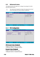
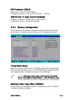
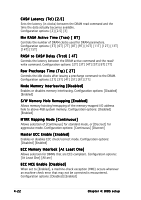
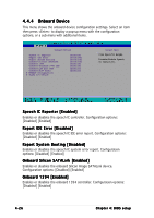
CAS# Latency (Tcl) [2.5] Sets the latency (in clocks) between the DRAM read command and the time the data actually becomes available. Configuration options: [2] [2.5] [3] Min RAS# Active Time (Tras) [ 8T] Controls the number of DRAM clocks used for DRAM parameters. Configuration options: [5T] [6T] [7T] [8T] [9T] [10T] [11T] [12T] [13T] [14T] [15T] RAS# to CAS# Delay (Trcd) [ 4T] Controls the latency between the DRAM active command and the read/ write command. Configuration options: [2T] [3T] [4T] [5T] [6T] [7T] Row Precharge Time (Trp) [ 2T] Controls the idle clocks after issuing a precharge command to the DRAM. Configuration options: [2T] [3T] [4T] [5T] [6T] [7T] Node Memory Interleaving [Disabled] Enables or disables memory interleaving. Configuration options: [Disabled] [Enabled] S/W Memory Hole Remapping [Enabled] Allows memory hoisting/remapping of the memory-mapped I/O address hole to above 4GB system memory. Configuration options: [Disabled] [Enabled] MTRR Mapping Mode [Continuous] Allows selection of [Continuous] for standard mode, or [Discreet] for aggressive mode. Configuration options: [Continuous] [Discreet] Master ECC Enable [Enabled] Enables or disables ECC check/correct mode. Configuration options: [Disabled] [Enabled] ECC Memory Interlock [At Least One] Allows selection for DIMMs that are ECC-compliant. Configuration options: [At Least One] [All are] ECC MCE Enable [Disabled] When set to [Enabled], a machine-check exception (#MC) occurs whenever an machine-check error that may not be corrected is encountered. Configuration options: [Disabled] [Enabled] 4-22 Chapter 4: BIOS setup
-
 1
1 -
2
-
3
-
4
-
5
-
6
-
7
-
8
-
9
-
10
-
11
-
12
-
13
-
14
-
15
-
16
-
17
-
18
-
19
-
20
-
21
-
22
-
23
-
24
-
25
-
26
-
27
-
28
-
29
-
30
-
31
-
32
-
33
-
34
-
35
-
36
-
37
-
38
-
39
-
40
-
41
-
42
-
43
-
44
-
45
-
46
-
47
-
48
-
49
-
50
-
51
-
52
-
53
-
54
-
55
-
56
-
57
-
58
-
59
-
60
-
61
-
62
-
63
-
64
-
65
-
66
-
67
-
68
-
69
-
70
-
71
-
72
-
73
-
74
-
75
-
76
-
77
-
78
-
 79
79 -
 80
80 -
 81
81 -
 82
82 -
 83
83 -
 84
84 -
 85
85 -
 86
86 -
 87
87 -
 88
88 -
 89
89 -
90
-
91
-
92
-
93
-
94
-
95
-
96
-
97
-
98
-
99
-
100
-
101
-
102
-
103
-
104
-
105
-
106
-
107
-
108
-
109
-
110
-
111
-
112
 |
 |