Asus RS100-E5 User Guide
Asus RS100-E5 - 0 MB RAM Manual
 |
UPC - 610839665518
View all Asus RS100-E5 manuals
Add to My Manuals
Save this manual to your list of manuals |
Asus RS100-E5 manual content summary:
- Asus RS100-E5 | User Guide - Page 1
RS100-E5-PI2 1U Rackmount Server User Guide - Asus RS100-E5 | User Guide - Page 2
COMPUTER INC. All Rights Reserved. No part of this manual, including the products and software described in ASUS. ASUS assumes no responsibility or liability for any errors or inaccuracies that may appear in this manual, including the products and software described in it. Product warranty or service - Asus RS100-E5 | User Guide - Page 3
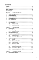
Contents Contents...iii Notices...vii Safety information viii About this guide ix Chapter 1: Product introduction 1.1 System package contents 1-2 (CPU 2-6 2.3.1 Installing the CPU 2-6 2.3.2 Installing the CPU heatsink 2-8 2.4 System memory 2-10 2.4.1 Overview 2-10 2.4.2 Memory configurations - Asus RS100-E5 | User Guide - Page 4
panel connectors 4-7 4.3.2 Internal connectors 4-8 Chapter 5: BIOS setup 5.1 Managing and updating your BIOS 5-2 5.1.1 Creating a bootable floppy disk 5-2 5.1.2 AFUDOS utility 5-3 5.1.3 ASUS CrashFree BIOS 3 utility 5-6 5.2 BIOS setup program 5-8 5.2.1 BIOS menu screen 5-9 5.2.2 Menu bar - Asus RS100-E5 | User Guide - Page 5
Trusted Computing 5-18 5.4.4 MPS Configuration 5-18 5.4.5 CPU Configuration 5-19 5.4.6 Chipset Configuration 5-20 5.4.7 RAID configuration 6.1 RAID configurations 6-2 6.1.1 RAID definitions 6-2 6.1.2 Installing Serial ATA hard disks 6-3 6.1.3 Setting the RAID item in BIOS 6-3 6.1.4 RAID - Asus RS100-E5 | User Guide - Page 6
the boot drive from a RAID set 6-29 Enabling the WriteCache 6-30 Chapter 7: Driver installation 7.1 RAID driver installation 7-2 7.1.1 Creating a RAID driver disk 7-2 7.1.2 Installing the RAID controller driver 7-4 7.2 LAN driver installation 7-14 7.2.1 Windows® Server 7-14 7.2.2 Red Hat - Asus RS100-E5 | User Guide - Page 7
to comply with the limits for a Class B digital device, pursuant to Part 15 of the FCC Rules. These limits are designed to provide reasonable and, if not installed and used in accordance with manufacturer' s instructions, may cause harmful interference to radio communications. However, there is no - Asus RS100-E5 | User Guide - Page 8
by yourself. Contact a qualified service technician or your dealer. Operation Safety • Any mechanical operation on this server must be conducted by certified or experienced engineers. • Before operating the server, carefully read all the manuals included with the server package. • Before using the - Asus RS100-E5 | User Guide - Page 9
and describes the BIOS parameters. 6. Chapter 6: RAID configuration This chapter tells how to change system settings through the BIOS Setup menus. Detailed descriptions of the BIOS parameters are also provided. 7 Chapter 7: Driver installation This chapter provides instructions for installing the - Asus RS100-E5 | User Guide - Page 10
when trying to complete a task. IMPORTANT: Instructions that you MUST follow to complete a task. format A:/S References Refer to the following sources for additional information, and for product and software updates. 1. ASUS Server Web-based Management (ASWM) user guide This manual - Asus RS100-E5 | User Guide - Page 11
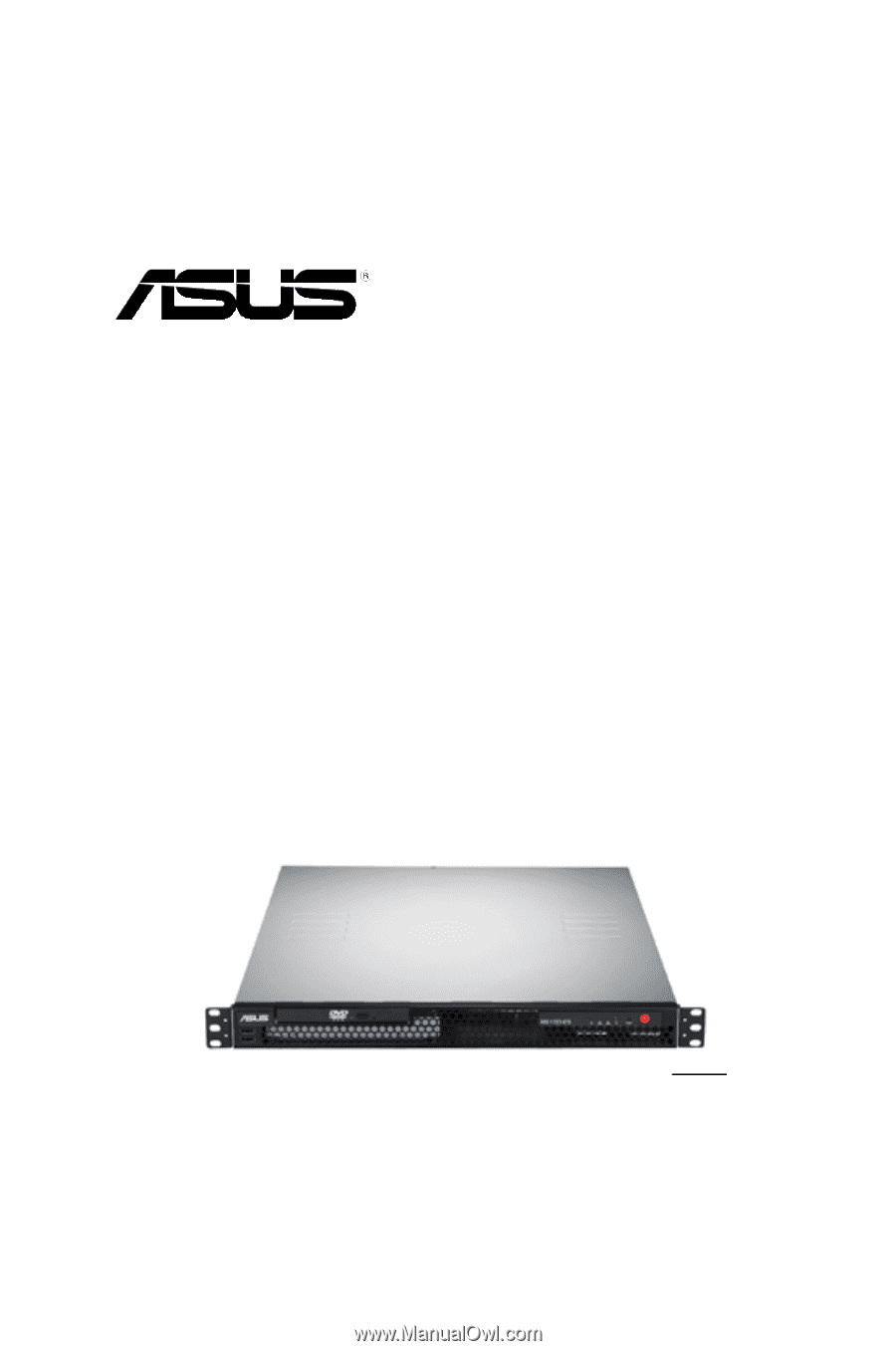
Product introduction Chapter 1 This chapter describes the general features of the chassis kit. It includes sections on front panel and rear panel specifications. ASUS RS100-E5-PI2 1- - Asus RS100-E5 | User Guide - Page 12
-E5-PI2 ASUS R09 1U Rackmount Chassis ASUS P5BV-M/RS100-E5 Server Board 1 x 220W 80+ Single Power Supply 2 x SATA Cables 1 x PCI Express x16 Riser Card (x8 link) 1 x Front I/O Board (ASUS FPB-R9) 1 x USB Board (ASUS USB-R9) 2 x System Fans (2 x 40x28) 1 x CPU Heatsink 1 x RS100-E5-PI2 User's Guide - Asus RS100-E5 | User Guide - Page 13
The ASUS RS100-E5-PI2 is a 1U barebone server system featuring the ASUS P5BV-M/RS100-E5 server board. The server supports Intel - Supports software RAID 0 & 1 LSI MegaRAID (for Linux/Windows) - Supports software RAID 0 & 1 2 x Internal SATA2 HDD Bays 2 x Broadcom® BCM5721 PCI-E GbE LAN - Supports 10/ - Asus RS100-E5 | User Guide - Page 14
Software Management Hardware Solution Software Dimension (D x W x H) Net Weight Kg (CPU, DRAM & HDD not inclu ded) Power Supply Environment CA® eTrust™ anti-virus software (Optional) SM-Bus/ASMB3-SOL or ASMB3-iKVM (Optional) ASUS ASWM 2.0® 381mm x 430mm x 43.4mm 6.2 Kg 220W 80+ PFC PSU - Asus RS100-E5 | User Guide - Page 15
panel features The barebone server displays a simple rear panel includes the expansion slots, and system power socket. The middle part includes the I/O shield with openings for the rear panel connectors on the port is for ASUS ASMB3-SOL or ASMB3-iKVM controller card only. ASUS RS100-E5-PI2 1-5 - Asus RS100-E5 | User Guide - Page 16
6 1. PCI Express x16 Riser Card (at x8 link) 2. Chassis fans (x 2) 3. ASUS P5BV-M/RS100-E5 Server Board 4. Power supply 5. HDD tray 2 (hidden) and Slim-type Optical drive (optional) 6. HDD tray 1 • The barebone server does not include a floppy disk drive. connect a USB floppy disk drive to any of - Asus RS100-E5 | User Guide - Page 17
Status Description OFF No link GREEN Linked BLINKING Data activity SPEED LED Status Description OFF 10 Mbps connection ORANGE 100 Mbps connection GREEN 1 Gbps connection ASUS RS100-E5-PI2 1-7 - Asus RS100-E5 | User Guide - Page 18
1-8 Chapter 1: Product introduction - Asus RS100-E5 | User Guide - Page 19
Hardware setup Chapter 2 This chapter lists the hardware setup procedures that you have to perform when installing or removing system components. ASUS RS100-E5-PI2 2- - Asus RS100-E5 | User Guide - Page 20
2.1 Chassis cover 2.1.1 Removing the cover 1. Use a Phillips screwdriver to remove the screw on the top cover. 2. Firmly hold the cover and slide it toward the rear panel for about half an inch until it is disengaged from the chassis. 3. Lift the cover from the chassis. 2-2 Chapter 2: Hardware - Asus RS100-E5 | User Guide - Page 21
2.1.2 Installing the cover 1. Position the cover on top of the chassis with the hooks aligned to the side tabs of the chassis. Side tabs 2. Slide the cover toward the front until it snaps in place. ASUS RS100-E5-PI2 2-3 - Asus RS100-E5 | User Guide - Page 22
3. Secure the cover with one screw. 2-4 Chapter 2: Hardware setup - Asus RS100-E5 | User Guide - Page 23
Information for detailed Information. Place this side towards the rear of the chassis ® P5BV-M/RS100-E5 Make sure to unplug the power cord before installing or removing the motherboard. Failure to do so can cause you physical injury and damage motherboard components. ASUS RS100-E5-PI2 2-5 - Asus RS100-E5 | User Guide - Page 24
/transit-related. • Keep the cap after installing the motherboard. ASUS will process Return Merchandise Authorization (RMA) requests only if the the CPU To install a CPU: 1. Locate the CPU socket on the motherboard. ® P5BV-M/RS100-E5 P5BV-M/RS100-E5 CPU Socket 775 Before installing the CPU, make - Asus RS100-E5 | User Guide - Page 25
cap from the load B plate window to remove (B). Load plate 5. Position the CPU over the socket, making sure that the gold triangle is on the bottom-left corner of the socket. The socket alignment key should fit into the CPU notch. Alignment key Gold triangle mark ASUS RS100-E5-PI2 A 2-7 - Asus RS100-E5 | User Guide - Page 26
on the socket and damaging the CPU! 6. Close the load plate (A), then A push the load lever (B) until it snaps into the retention tab. B The motherboard supports Intel® Xeon® 3300/3200/3100/3000 series processors with the Intel® Enhanced Memory 64 Technology (EM64T), and Enhanced Intel - Asus RS100-E5 | User Guide - Page 27
2. Tighten the screws. 3. Peel the adhesive cover of the heatsink plastic cover and evenly attach to heatsink. Heatsink plastic cover The heatsink plastic cover ensures the linear airflow between the heatsink and chassis fans. ASUS RS100-E5-PI2 2-9 - Asus RS100-E5 | User Guide - Page 28
: DIMM_A1 DIMM_A2 ® P5BV-M/RS100-E5 128 Pins 112 Pins DIMM_B1 DIMM_B2 P5BV-M/RS100-E5 240-pin DDR2 DIMM Sockets 2.4.2 Memory configurations You may install we recommend that you obtain memory modules from the same vendor. Refer to the DDR2 Qualified Vendors List on the ASUS web site. • When - Asus RS100-E5 | User Guide - Page 29
1. Simultaneously press the retaining clips outward to unlock the DIMM. Support the DIMM lightly with your fingers when pressing the retaining clips. The DIMM might get damaged when it flips out with extra force. 2 1 1 2. Remove the DIMM from the socket. DDR2 DIMM notch ASUS RS100-E5-PI2 2-11 - Asus RS100-E5 | User Guide - Page 30
2.5 Replaceable components You may need to replace defective components or remove previously installed system components when installing or removing system devices. This section tells how to install or remove the following components: 1. Chassis fans 2. Serial ATA hard disk drives 3. Optical disk - Asus RS100-E5 | User Guide - Page 31
can install up to two (2) Serial ATA hard disk drives to the system. Follow the succeeding instructions to install each of the drives. To install primary Serial ATA drive: 1. Locate the Serial ATA drive bay beside the power supply unit. Notice the four standard screw holes. ASUS RS100-E5-PI2 2-13 - Asus RS100-E5 | User Guide - Page 32
2. Connect the Serial ATA signal cable and ATX power connectors. Use the L-type Serial ATA connector to connect to the hard drive. SATA L-type connector ATX power connector SATA signal cable 3. Place the Serial ATA drive into the drive bay matching the four screw holes with the holes on the disk - Asus RS100-E5 | User Guide - Page 33
below for the location of SATA1 connector. ® P5BV-M/RS100-E5 SATA1 GND RSATA_RXN1 RSATA_RXP1 GND RSATA_TXN1 RSATA_TXP1 GND P5BV-M/RS100-E5 SATA1 Connector To install secondary Serial ATA drive: hard disk drive brackets to the HDD with four screws. HDD bracket ASUS RS100-E5-PI2 2-15 - Asus RS100-E5 | User Guide - Page 34
7. Connect the other end of the Serial ATA signal connector to the onboard SATA connector labeled SATA3. ATX power connector SATA signal cable ® P5BV-M/RS100-E5 SATA3 GND RSATA_RXN1 RSATA_RXP1 GND RSATA_TXN1 RSATA_TXP1 GND P5BV-M/RS100-E5 SATA3 Connector 2-16 Chapter 2: Hardware setup - Asus RS100-E5 | User Guide - Page 35
hole of the ODD bracket with the screw hole on the SATA drive bracket, then secure it with a screw. ODD bracket Optical disk drive (optional) ASUS RS100-E5-PI2 2-17 - Asus RS100-E5 | User Guide - Page 36
4. Place the ODD side bracket to the ODD, matching the two connectors of the bracket with the holes on the side of the ODD. Bracket connectors ODD side bracket 5. Secure the ODD side bracket to the Serial SATA drive bracket with a screw. 6. Connect the 80-pin IDE cable black connector and 4-pin - Asus RS100-E5 | User Guide - Page 37
Installation options Chapter 3 This chapter describes how to install the optional components and devices into the barebone server. ASUS RS100-E5-PI2 2- - Asus RS100-E5 | User Guide - Page 38
kit contains two pairs of rails (one pair for each side of the server system), six (6) pieces of inner rail screws, and two (2) pieces of rack screws. Outer rails Inner rails Rack screws Inner rail screws 3.1.1 Attaching the rack ears The bundled rack ears serve as handle when inserting or pulling - Asus RS100-E5 | User Guide - Page 39
four screws. 5. Repeat steps 2 - 4 to attach the other rack ear. 3.1.2 Attaching the rails to the rack To attach the rack rails: 1. Attach the inner rail to the correspoding side of the chassis and secure with three inner rail screws. Make sure the rail is oriented as shown. ASUS RS100-E5-PI2 3-3 - Asus RS100-E5 | User Guide - Page 40
the other side of the chassis and secure with three inner rail screws. 3. Select one unit of space (1U) on the rack where you wish to install the server. 4. Place three (3) nuts on the front and three at the back. Do the same to the corresponding side of the rack. Nuts 5. Adjust the - Asus RS100-E5 | User Guide - Page 41
the server on both sides. Slide the latches on the inner rack rails to the direction indicated below. Hold the latches, and insert the rear side of the server to the front end of the outer rack rail. Make sure that the inner rails are properly aligned with the outer rails. ASUS RS100-E5-PI2 3-5 - Asus RS100-E5 | User Guide - Page 42
9. Carefully push the server all the way to the back until the front panel fits the front end of the rack. 10. Secure the server to the rack with one rack screw at one side. Secure the other side as well. Rack screw 3-6 Chapter 3: Installation options - Asus RS100-E5 | User Guide - Page 43
provides a convenient and economical way to install the server to the rack cabinet. 3.2.1 Attaching the long rack ears The long rack ears are used to support the server system in a rack cabinet. To attach the with six screws. 5. Repeat steps 2 - 4 to attach the other rack ear. ASUS RS100-E5-PI2 3-7 - Asus RS100-E5 | User Guide - Page 44
the rack cabinet 1. Select one unit of space (1U) on the rack where you wish to install the server. 2. Place three (3) nuts on the front and three at the back. Do the same to the corresponding side of the rack. Nuts 3. Carefully place the server to the desired position on the rack. 4. Secure - Asus RS100-E5 | User Guide - Page 45
the front server panel. 1. Prepare the bundled pair of front panel connectors and a set of twelve (12) screws. 2. Secure the front panel connector to the rack ear. 3. Secure the rack ear to the chassis with four screws. 4. Repeat steps 2 - 3 to attach the other rack ear. ASUS RS100-E5-PI2 3-9 - Asus RS100-E5 | User Guide - Page 46
5. Align the front cover to the preinstalled front cover connectors. 6. Carefully attach the front cover to the front cover connectors. 3-10 Chapter 3: Installation options - Asus RS100-E5 | User Guide - Page 47
Motherboard Info Chapter 4 This chapter gives inforamtion about the motherboard that comes with the server. This chapter includes the motherboard layout, jumper settings, and connector locations. ASUS RS100-E5-PI2 4-1 - Asus RS100-E5 | User Guide - Page 48
(9.6in) ATX12V1 ISL 6312 COM1 VGA1 BCM 5721 BCM 5721 Intel 3200 MCH ® P5BV-M/RS100-E5 DDR2 DIMM_A1 (64 bit,240-pin module) LAN1 DDR2 DIMM_A2 (64 bit,240-pin COM2 HDLED1 PCIE2 PCI3 PCI4 FLOPPY1 ASMB3 Super I/O 8Mb BIOS ICS 9LPRS918BKL Intel ICH7R ICH TPM1 AUX_PANEL1 USB34 RAID_SEL1 - Asus RS100-E5 | User Guide - Page 49
Slots 1. 2. CPU socket DDR2 DIMM slots Page 2-6 2-10 Jumpers 1. Clear RTC RAM (CLRTC1) 2. RAID controller selection (3-pin RAID_SEL1) 3. Force BIOS recovery setting (3-pin Page 4-7 4-7 4-7 4-7 4-7 4-7 4-7 4-7 Page 4-8 4-9 4-10 4-11 4-11 4-12 4-12 4-13 4-14 4-15 4-16 ASUS RS100-E5-PI2 4-3 - Asus RS100-E5 | User Guide - Page 50
memory RS100-E5 CLRTC1 12 23 Normal (Default) P5BV-M/RS100-E5 Clear RTC RAM Clear CMOS • You do not need to clear the RTC when the system hangs due to overclocking. For system failure due to overclocking, use the C.P.R. (CPU Parameter Recall) feature. Shut down and reboot the system so the BIOS - Asus RS100-E5 | User Guide - Page 51
to pins 2-3. 3. Insert the floppy disk then turn on the system to update the BIOS. 4. Shut down the system. 5. Set the jumper back to pins 1-2. 6. Turn on the system. ® P5BV-M/RS100-E5 RECOVERY1 12 23 Normal (Default) BIOS recovery P5BV-M/RS100-E5 BIOS Recovery Setting ASUS RS100-E5-PI2 4-5 - Asus RS100-E5 | User Guide - Page 52
3-pin or a 4-pin fan cable plug to the CPU fan or Chasis fan connectors Set these jumpers to pins 1-2 Short PWM mode if you are using a 4-pin fan cable plug, or to pins 2‑3 Short DC mode if you are using a 3-pin plug. ® P5BV-M/RS100-E5 P5BV-M/RS100-E5 Fan Mode Setting CPUFAN_SET1 12 23 PWM Mode - Asus RS100-E5 | User Guide - Page 53
BLINKING Data activity Speed LED Status Description OFF 10 Mbps connection ORANGE 100 Mbps connection GREEN 1 Gbps connection ACT/LINK SPEED LED LED LAN port ASUS RS100-E5-PI2 4-7 - Asus RS100-E5 | User Guide - Page 54
the other end to the signal connector at the back of the floppy disk drive. ® P5BV-M/RS100-E5 FLOPPY1 PIN1 NOTE: Orient the red markings on the floppy ribbon cable to PIN 1. P5BV-M/RS100-E5 Floppy Disk Drive Connector Pin 5 on the connector is removed to prevent incorrect cable connection when - Asus RS100-E5 | User Guide - Page 55
its jumper accordingly. Refer to the hard disk documentation for the jumper settings. PRI_IDE1 ® P5BV-M/RS100-E5 PIN 1 P5BV-M/RS100-E5 IDE Connector NOTE: Orient the red markings (usually zigzag) on the IDE ribbon cable conductor IDE cable for Ultra DMA 100/66 IDE devices. ASUS RS100-E5-PI2 4-9 - Asus RS100-E5 | User Guide - Page 56
RAID 0 and RAID 1 configuration using the Intel® Matrix Storage Technology or the LSI MegaRAID® utility embedded in the Intel® ICH7R Southbridge. ® P5BV-M/RS100-E5 to create a Serial ATA RAID set using these connectors, set the Configure SATA as item in the BIOS to [RAID]. See section 4.3.4 IDE - Asus RS100-E5 | User Guide - Page 57
(10-1 pin USB34) This connector is for USB 2.0 ports. This USB connector complies with USB 2.0 specification that supports up to 480 Mbps connection speed. USB+5V USB_P3USB_P3+ GND ® P5BV-M/RS100-E5 USB34 P5BV-M/RS100-E5 USB 2.0 Connector USB+5V USB_P4USB_P4+ GND NC ASUS RS100-E5-PI2 4-11 - Asus RS100-E5 | User Guide - Page 58
back of the system chassis. The serial port module is purchased separately. ® P5BV-M/RS100-E5 COM2 PIN 1 P5BV-M/RS100-E5 COM2 Port Connector 7. CPU and system fan connectors (4-pin CPU_FAN1, FRNT_FAN1, REAR_FAN1) The fan connectors support cooling fans of 350 mA ~ 740 mA (8.88 W max.) or a total - Asus RS100-E5 | User Guide - Page 59
Volts +3 Volts GND GND ® P5BV-M/RS100-E5 +3 Volts -12 Volts Ground PSON# Ground Ground Ground -5 Volts +5 Volts +5 Volts +5 Volts Ground +12V DC +12V DC P5BV-M/RS100-E5 ATX Power Connector • Use of an with a higher power rating if you intend to install additional devices. ASUS RS100-E5-PI2 4-13 - Asus RS100-E5 | User Guide - Page 60
PANEL1) This connector supports several chassis-mounted the system in sleep or soft-off mode depending on the BIOS settings. Pressing the power switch for more than four seconds ® P5BV-M/RS100-E5 PANEL1 HDLED+ HDLEDNMIBTN# GND POWERBTN# GND NC RESETBTN# GND 4 5 6 P5BV-M/RS100-E5 System - Asus RS100-E5 | User Guide - Page 61
connector (20-2 pin AUX_PANEL1) This connector supports several server system functions. AUX_PANEL1 1 22 ® P5BV-M/RS100-E5 NC I2CCLK1 GND I2CDATA1 +5VSB LAN1_LINKACTLEDLAN1_LINKACTLED+ is for the locator button. This button queries the state of the system locator. ASUS RS100-E5-PI2 4-15 - Asus RS100-E5 | User Guide - Page 62
Trusted Platform Module (TPM) Card. You need to install ASUS TPM card to use this feature function. ® P5BV-M/RS100-E5 TPM PCICLK FRAME# PCIRST# AD3 3.3V AD0 NC 3.3VSB GND PWRDW# GND NC AD2 AD1 GND NC SERIRQ# CLKRUN# NC P5BV-M/RS100-E5 TPM Connector The TPM module is purchased separately. 4-16 - Asus RS100-E5 | User Guide - Page 63
Chapter 5 This chapter tells how to change the system settings through the BIOS Setup menus. Detailed descriptions of the BIOS parameters are also provided. BIOS Setup ASUS RS100-E5-PI2 5-1 - Asus RS100-E5 | User Guide - Page 64
and update the motherboard Basic Input/Output System (BIOS) setup. 1. ASUS AFUDOS (Updates the BIOS in DOS mode using a bootable floppy disk.) 2. ASUS CrashFree BIOS 3 (Updates the BIOS using a bootable floppy or USB Flash disk when the BIOS file fails or gets corrupted.) Refer to the corresponding - Asus RS100-E5 | User Guide - Page 65
/oOLDBIOS1.rom AMI Firmware Update Utility - Version 1.19(ASUS V2.07(03.11.24BB)) Copyright (C) 2002 American Megatrends, Inc. All rights reserved. Reading flash ..... done Write to file...... ok A:\> The utility returns to the DOS prompt after copying the current BIOS file. ASUS RS100-E5-PI2 5-3 - Asus RS100-E5 | User Guide - Page 66
(www.asus.com) and download the latest BIOS file for the motherboard. Save the BIOS file to a bootable floppy disk. Write the BIOS filename on a piece of paper. You need to type the exact BIOS filename at the DOS prompt. 2. Copy the AFUDOS utility (afudos.exe) from the motherboard support CD to - Asus RS100-E5 | User Guide - Page 67
drive. 3. Boot the system from the support CD, then select the FreeDOS command prompt. 4. At the DOS prompt, replace the prompt with the USB flash disk drive letter, then type: afudos /i[filename] 5. Follow the instructions in the previous section to update the BIOS file. ASUS RS100-E5-PI2 5-5 - Asus RS100-E5 | User Guide - Page 68
when found, the utility reads the BIOS file and starts flashing the corrupted BIOS file. 4. Restart the system after the utility completes the updating process. • Only the USB flash disk with FAT 32/16 format and single partition can support ASUS CrashFree BIOS 3. The device size should be smaller - Asus RS100-E5 | User Guide - Page 69
... Checking for floppy... Floppy found! Reading file "rs100e5.rom". Completed. Start flashing... DO NOT shut down or reset the system while updating the BIOS! Doing so can cause system boot failure! 4. Restart the system after the utility completes the updating process. ASUS RS100-E5-PI2 5-7 - Asus RS100-E5 | User Guide - Page 70
supports a programmable firmware chip that you can update using the provided utility described in section 5.1 Managing and updating your BIOS. Use the BIOS your system using the BIOS Setup program so The default BIOS settings for any BIOS settings Exit Menu. • The BIOS setup screens shown in this - Asus RS100-E5 | User Guide - Page 71
menu screen Menu items Menu bar Configuration fields General help BIOS SETUP UTILITY Main Advanced Power Boot Exit System Time System Date Legacy Diskette A Primary IDE Master the settings. Some of the navigation keys differ from one screen to another. ASUS RS100-E5-PI2 5-9 - Asus RS100-E5 | User Guide - Page 72
. 5.2.9 General help At the top right corner of the menu screen is a brief description of the selected item. Pop-up window Scroll bar 5-10 Chapter 5: BIOS setup - Asus RS100-E5 | User Guide - Page 73
system information. Refer to section 5.2.1 BIOS menu screen for information on the menu screen items and how to navigate through them. BIOS SETUP UTILITY Main Advanced Power Boot [360K, 5.25 in.] [1.2M , 5.25 in.] [720K , 3.5 in.] [1.44M, 3.5 in.] [2.88M, 3.5 in.] ASUS RS100-E5-PI2 5-11 - Asus RS100-E5 | User Guide - Page 74
Exit v02.58 (C)Copyright 1985-2007, American Megatrends, Inc. The BIOS automatically detects the values opposite the dimmed items (Device, Vendor, Size enables the LBA mode if the device supports this mode, and if the device was not previously formatted with LBA mode disabled. Configuration options: - Asus RS100-E5 | User Guide - Page 75
Enter> if you wish to configure the item. Main IDE Configuration ATA/IDE Configuration Configure SATA as BIOS SETUP UTILITY [Enhanced] [IDE] Hard Disk Write Protect [Disabled] IDE Detect Time Out (Sec set the SATA configuration. Configuration options: [IDE] [RAID] [AHCI] ASUS RS100-E5-PI2 5-13 - Asus RS100-E5 | User Guide - Page 76
this item to [AHCI]. The AHCI allows the onboard storage driver to enable advanced Serial ATA features that increases storage performance on to [RAID]. Hard Disk Write Protect [Disabled] Enables or disables the device write protection. This will be effective only if device is accessed through BIOS. - Asus RS100-E5 | User Guide - Page 77
. Processor Displays the auto-detected CPU specification. System Memory Displays the auto-detected total system memory. The System information screen may be not exactly match the information on your screen. It will change according to your actual system configuration. ASUS RS100-E5-PI2 5-15 - Asus RS100-E5 | User Guide - Page 78
the system to malfunction. Main Advanced BIOS SETUP UTILITY Power Boot Exit USB Configuration Remote Access Configuration Trusted Computing MPS Configuration CPU Configuration Chipset Onboard Devices Configuration PCIPnP Configure the USB support. Select Screen Select Item +- Change - Asus RS100-E5 | User Guide - Page 79
options: [HiSpeed] [FullSpeed] BIOS EHCI Hand-Off [Enabled] Allows yout to enable or disable the BIOS EHCI Hand-Off support function. Configuration options: [ serial port mode. Configuration options: [115200 8,n,1] [57600 8,n,1] [38400 8,n,1] [19200 8,n,1] [09600 8,n,1] ASUS RS100-E5-PI2 5-17 - Asus RS100-E5 | User Guide - Page 80
/ VT100 terminals. Configuration options: [Enabled] [Disabled] 5.4.3 Trusted Computing Advanced BIOS SETUP UTILITY Trusted Computing TCG/TPM SUPPORT [No] TCG/TPM SUPPORT [No] Allows you to set the TCG/TPM SUPPORT. Configuration options: [No] [Yes] Enable/Disable TPM TCG (TPM 1.1/1.2) supp - Asus RS100-E5 | User Guide - Page 81
CPU-related information that the BIOS automatically detects. Advanced BIOS SETUP UTILITY Configure advanced CPU settings Module Version: 3D.06 Manufacturer: Intel Brand String: Intel(R) Xeon(R) CPU X3230 @ 2.66GHz Frequency : 2.66GHz actual CPU type. C1E Support [Enabled ASUS RS100-E5-PI2 5-19 - Asus RS100-E5 | User Guide - Page 82
North Bridge Configuration Advanced BIOS SETUP UTILITY North Bridge chipset Configuration Memory Remap Feature [Enabled] according to the DRAM SPD (Serial Presence Detect). When disabled, you can manually set the DRAM timing parameters through the DRAM sub-items. Configuration options: [ - Asus RS100-E5 | User Guide - Page 83
Boot ROM PCIE LAN-5721B LAN5721B Boot ROM [Enabled] [Disabled] [Enabled] [Disabled] Allows BIOS to Select Serial Port1 Base Addresses. Serial Port1 Address [3F8/IRQ4] Allows you to select the to select the Serial Port2 mode. Configuration options: [Normal] [IrDA] [ASK IR] ASUS RS100-E5-PI2 5-21 - Asus RS100-E5 | User Guide - Page 84
A is LAN port 2 supporting ASF, and LAN B is LAN port 1 not supporting ASF. Configuration options: [ PnP or legacy ISA devices, and setting the memory size block for legacy ISA devices. Take caution Plug And Play O/S [No] When set to [No], BIOS configures all the devices in the system. When set to - Asus RS100-E5 | User Guide - Page 85
an IRQ to PCI VGA card if the card requests for an IRQ. When set to [No], BIOS does not assign an IRQ to the PCI VGA card even if requested. Configuration options: [No] [ [Reserved], the IRQ is reserved for legacy ISA devices. Configuration options: [PCI Device] [Reserved] ASUS RS100-E5-PI2 5-23 - Asus RS100-E5 | User Guide - Page 86
) features. Select an item then press to display the configuration options. Main Advanced BIOS SETUP UTILITY Power Boot Exit ACPI 2.0 Support ACPI APIC Support APM Configuration Hardware Monitor [Disabled] [Enabled] Add additional tables as per ACPI 2.0 specifications. Select - Asus RS100-E5 | User Guide - Page 87
5.5.1 APM Configuration Power BIOS SETUP UTILITY APM Configuration Restore on AC Power Loss [Last State] Resume On Ring Resume On PME# Resume On RTC Alarm this item and press the or key to make the selection. Configuration options: [00] [01] [02] [03]...[59] ASUS RS100-E5-PI2 5-25 - Asus RS100-E5 | User Guide - Page 88
BIOS SETUP UTILITY Hardware Monitor CPU Temperature MB Temperature [43ºC/109ºF] [35ºC/95ºF] CPU_Fan1 Speed CPU Smart Fan Control CPU Fan Ratio CPU the motherboard, the field shows N/A. CPU Smart Fan Control [Enabled] Allows you to enable or disable the ASUS Smart Fan feature that smartly adjusts - Asus RS100-E5 | User Guide - Page 89
speed will be adjusted to maintain the CPU temperature as low as the selected temperature. Configuration options: [35ºC] [38ºC] [41ºC] [44ºC] [47ºC] [50ºC] [53ºC] The onboard hardware monitor automatically detects the voltage outputs through the onboard voltage regulators. ASUS RS100-E5-PI2 5-27 - Asus RS100-E5 | User Guide - Page 90
menu. Main Advanced Boot Settings Power Boot Device Priority BIOS SETUP UTILITY Boot Exit Specifies the Boot Device Priority sequence , American Megatrends, Inc. 5.6.1 Main Boot Device Priority Advanced Power BIOS SETUP UTILITY Boot Exit Boot Device Priority 1st Boot Device 2nd Boot - Asus RS100-E5 | User Guide - Page 91
Support Wait For 'F1' If Error Hit 'DEL' Message Display Interrupt 19 Capture BIOS SETUP UTILITY Boot [Enabled] [Enabled] [Force BIOS] [On] [Auto] [Enabled] [Enabled] [Enabled] Allows BIOS the option ROMs to trap Interrupt 19. Configuration options: [Disabled] [Enabled] ASUS RS100-E5-PI2 5-29 - Asus RS100-E5 | User Guide - Page 92
password. To clear the supervisor password, select the Change Supervisor Password then press . The message "Password Uninstalled" appears. If you forget your BIOS password, you can clear it by erasing the CMOS Real Time Clock (RTC) RAM. See section 2.6 Jumper for information on how to erase - Asus RS100-E5 | User Guide - Page 93
clear the user password. Password Check [Setup] When set to [Setup], BIOS checks for user password when accessing the Setup utility. When set to [Always], BIOS checks for user password both when accessing Setup and booting the system. Configuration options: [Setup] [Always] ASUS RS100-E5-PI2 5-31 - Asus RS100-E5 | User Guide - Page 94
the changes that you made to the Setup program. If you made changes to fields other than System Date, System Time, and Password, the BIOS asks for a confirmation before exiting. Discard Changes This option allows you to discard the selections you made and restore the previously saved values. After - Asus RS100-E5 | User Guide - Page 95
RAID Configuration Chapter 6 This chapter provides instructions for setting up, creating and configuring RAID sets using the available utilities. ASUS RS100-E5-PI2 6-1 - Asus RS100-E5 | User Guide - Page 96
hard disk drives is required for this setup. RAID 1 (Data mirroring) copies and maintains an identical image of data from one drive to a second system from a hard disk drive included in a created RAID set, copy first the RAID driver from the support CD to a floppy disk before you install an operating - Asus RS100-E5 | User Guide - Page 97
set under Windows® Server operating system. Use the LSI Software RAID Configuration Utility to create a RAID 0 or RAID 1 under Windows® Server or Red Hat® Enterprise operating system. Refer to the succeeding sections for details on how to use the RAID configuration utilities. ASUS RS100-E5-PI2 6-3 - Asus RS100-E5 | User Guide - Page 98
allows you to create RAID 0 or RAID 1 from Serial ATA hard disk drives that are connected to the Serial ATA connectors supported by the Southbridge. To to move through the menus and select the menu options. The RAID BIOS setup screens shown in this section are for reference only and may not - Asus RS100-E5 | User Guide - Page 99
stripe size for server systems, and a higher stripe size for multimedia computer systems used mainly for audio and video editing. 5. Key in the RAID volume capacity that to create the RAID volume and return to the main menu, or to go back to the Create Volume menu. ASUS RS100-E5-PI2 6-5 - Asus RS100-E5 | User Guide - Page 100
N/A XX.X GB Create Volume [ HELP ] Enter a string between 1 and 16 characters in length that can be used to uniquely identify the RAID volume. This name is case sensitive and cannot contain special characters. [↑↓]-Change [TAB]-Next [ESC]-Previous Menu [Enter]-Select 2. Enter a name - Asus RS100-E5 | User Guide - Page 101
Menu []-Delete Volume 2. Use the up/down arrow key to select the RAID set you want to delete, then press . This window appears. [ 3. Press to delete the RAID set and return to the utility main menu; otherwise, press to return to the Delete Volume menu. ASUS RS100-E5-PI2 6-7 - Asus RS100-E5 | User Guide - Page 102
appears. 4. Press to reset the drive or press to return to the utility main menu. 5. Follow steps 2 to 4 to select and reset other RAID set drives. 6.2.5 Exiting the Intel® Matrix Storage Manager utility To exit the utility: 1. From the utility main menu, select 4. Exit, then press - Asus RS100-E5 | User Guide - Page 103
) 128KB 306.8GB Rebuild Yes Physical Disks: Port Drive Model 0 Hitachi HDS72161 3 Hitachi HDS72161 Serial # PVB300Z2R93D3D PVB300Z2R93D3D Size Type/Status(Vol ID) 153.4GB Non-RAID Disk 153.4GB Non-RAID Disk [↑↓]-Select [ESC]-Exit [ENTER]-Select Menu ASUS RS100-E5-PI2 6-9 - Asus RS100-E5 | User Guide - Page 104
and then follow the steps in section Rebuilding the RAID with other non-RAID disk on page 6-9. 6.2.7 Setting the Boot array in the BIOS Setup Utility You can set the boot priority sequence in the BIOS for your RAID arrays when creating multi-RAID using the Intel® Matrix Storage Manager. To set the - Asus RS100-E5 | User Guide - Page 105
legend box vary according to the menu level. LSI Software RAID Configuration Utility Ver A.53 Sep 06, 2007 Management Menu Configure Initialize Objects Rebuild Check Consistency Configure VD(s) Use Cursor Keys to Navigate Between Items And Press Enter To Select An Option ASUS RS100-E5-PI2 6-11 - Asus RS100-E5 | User Guide - Page 106
are set automatically including the size and stripe size (RAID 1 only). In New Configuration, you manually set the virtual drive parameters and assign the set size and stripe size (RAID 1 only). Using Easy Configuration To create a RAID set using the Easy Configuration option: 1. From the utility - Asus RS100-E5 | User Guide - Page 107
the available drives connected to the SATA ports. Select the drives you want to include in the RAID set, then press . When selected, the drive indicator changes from READY to ONLIN A[X]-[Y], where ENTER-EndArray,F10-Configure,F2-Drive Info,F3-Virtual Drives,F4-HSP ASUS RS100-E5-PI2 6-13 - Asus RS100-E5 | User Guide - Page 108
virtual drive information appears including a Virtual Drive menu that allows you to change the virtual drive parameters. LSI Software RAID Configuration Utility Ver A.53 Sep 06, 2007 Virtual Drive(s) Configured LD RAIEDasy CoSnifizgeuratio#nSt-riApReRsAY SELSEtCrTiIpOSNzMENU Status Managemen0t - Asus RS100-E5 | User Guide - Page 109
0 RAID = 1 Change DWC Off On Size = 156402MB DWC = Off RA = On Accept SPAN = NO Disk Write Cache Setting Of VD Use Cursor Keys To Navigate Between Items And Press Enter To Select An Option Enabling DWC can improve the performance, but with the risk of data loss. ASUS RS100-E5-PI2 6-15 - Asus RS100-E5 | User Guide - Page 110
the virtual drive configuration. When prompted, save the configuration, then press to return to the Management Menu. LSI Software RAID Configuration Utility Ver A.53 Sep 06, 2007 Configuration Menu Easy Configuration Management MNeenwu Configuration Configure View/Add Configuration Save - Asus RS100-E5 | User Guide - Page 111
Enter VDViSritzueal(MDBr)i:ve1506402 RAID = 1 Size = 156402MB DWC = Off RA = On Accept SPAN = NO Enter VD Size (MB): Use Cursor Keys To Navigate Between Items And Press Enter To Select An Option 6. Follow steps 8 to 13 of the previous section to create the RAID set. ASUS RS100-E5-PI2 6-17 - Asus RS100-E5 | User Guide - Page 112
Check Consistency Initialize Virtual Drive(s) Use Cursor Keys to Navigate Between Items And Press Enter To Select An Option 2. The screen displays the available RAID set and prompts you to select the virtual drive to initialize. Use the arrow keys to select the virtual drive from the Virtual Drive - Asus RS100-E5 | User Guide - Page 113
Check Consistency Virtual Drives Loical Drive 0 Virtual Drive(s) Configured LD RAID Size #Stripes StripSz Status 0 1 154494MB 2 64 KB ONLINE to Abort. Check Consistency ¦ 85 % Completed Virtual Drives Loical Drive 0 SPACE-(De)Select, F10-Initialize ASUS RS100-E5-PI2 6-19 - Asus RS100-E5 | User Guide - Page 114
initialize the virtual drive using the Objects command: 1. From the Management Menu, highlight Objects, then press . LSI Software RAID Configuration Utility Ver A.53 Sep 06, 2007 Management Menu Configure Initialize Objects Rebuild Check Consistency Configure Objects Like Adapter Parameters - Asus RS100-E5 | User Guide - Page 115
virtual drive to initialize from the Virtual Drives sub‑menu, then press . LSI Software RAID Configuration Utility Ver A.53 Sep 06, 2007 Vitual Drive(1) Virtual Drive 0 Objects Management MAednaupter Keys to Navigate Between Items And Press Enter To Select An Option ASUS RS100-E5-PI2 6-21 - Asus RS100-E5 | User Guide - Page 116
s Use Cursor Keys to Navigate Between Items And Press Enter To Select An Option 7. When initialization is completed, press . LSI Software RAID Configuration Utility Ver A.53 Sep 06, 2007 Vitual Drive(1) Virtual Drive 0 Objects Management MAednaupter Configure Virtual Drive Initialize - Asus RS100-E5 | User Guide - Page 117
manually rebuild failed hard disk drives using the Rebuild command in the Management Menu. To rebuild a failed hard disk drive: 1. From the Management Menu, highlight Rebuild, then press . LSI Software RAID -EndArray,F10-Configure,F2-Drive Info,F3-Virtual Drives,F4-HSP ASUS RS100-E5-PI2 6-23 - Asus RS100-E5 | User Guide - Page 118
F10>. The indicator for the selected drive now shows RBLD. LSI Software RAID Configuration Utility Ver A.53 Sep 06, 2007 Management Menu Configure Initialize When prompted, press to to rebuild the drive. LSI Software RAID Configuration Utility Ver A.53 Sep 06, 2007 REBUILD - PHYSICAL DRIVES - Asus RS100-E5 | User Guide - Page 119
2007 Management Menu Configure Initialize Objects Rebuild Check Consistency Virtual Drive(s) Configured LD RAID Size #Stripes StripSz Status 0 1 154494MB 2 64 KB ONLINE Virtual Drives Loical Drive 0 Select VD SPACE-(De)Select, F10-Check Consistency ASUS RS100-E5-PI2 6-25 - Asus RS100-E5 | User Guide - Page 120
Yes from the Consistency Check dialog box, then press . You may also press to check the drive consistency. LSI Software RAID Configuration Utility Ver A.53 Sep 06, 2007 Management Menu Configure Initialize Objects Rebuild Check Consistency Virtual Drives Virtual Drive 0 Virtual Drive - Asus RS100-E5 | User Guide - Page 121
prompted, use the arrow keys to select Yes from the dialog box to check the drive. 5. When checking is complete, press any key to continue. ASUS RS100-E5-PI2 6-27 - Asus RS100-E5 | User Guide - Page 122
, use the arrow keys to select Yes from the Clear Configuration? dialog box, then press . LSI Software RAID Configuration Utility Ver A.53 Sep 06, 2007 Configuration Menu Easy Configuration Management MNeenwu Configuration Configure View/Add CoCnlfiegaurraCtoinofniguration? Initialize - Asus RS100-E5 | User Guide - Page 123
to select the bootable virtual drive from the list, then press . LSI Software RAID Configuration Utility Ver A.53 Sep 06, 2007 Bootable VDs(1):Current Boot VD(0) ConfiguratiBoonotMeDnruive 0 3. The virtual drive is selected as boot drive. Press any key to continue. ASUS RS100-E5-PI2 6-29 - Asus RS100-E5 | User Guide - Page 124
6.3.7 Enabling the WriteCache You may enable the RAID controller's WriteCache option to improve the data transmission performance WC, then press to turn the option On (enabled). LSI Software RAID Configuration Utility Ver A.53 Sep 06, 2007 Adapter 0 Rebuild Rate = 30 ObjectsChk Const Rate = - Asus RS100-E5 | User Guide - Page 125
Driver installation Chapter 7 This chapter provides instructions for installing the necessary drivers for different system components. ASUS RS100-E5-PI2 7-1 - Asus RS100-E5 | User Guide - Page 126
drive or bootable array. This part provides instructions on how to install the RAID controller drivers during OS installation. 7.1.1 Creating a RAID driver disk You may have to use another system to create the RAID driver disk from the system/motherboard support CD or from the Internet. A floppy - Asus RS100-E5 | User Guide - Page 127
RS100-E5-PI2 system Back Exit Write DMI Write DMI RS100-E5-PI2 system Back Exit For systems with Red Hat® Enterprise versions that are not listed in the Makedisk menu, explore the support CD and copy the RAID driver disk from the following path: \ICH7R LSI RAID\Driver\Linux. ASUS RS100-E5-PI2 - Asus RS100-E5 | User Guide - Page 128
RAID controller driver Windows® Server OS During Windows® Server OS installation To install the RAID controller driver when installing Windows® Server OS: 1. Boot the computer using the Windows® Server have chosen to manually specify an adapter. Currently, Setup will load support for the following - Asus RS100-E5 | User Guide - Page 129
Windows, using a device support disk provided by an adapter manufacturer. Select the SCSI Adapter you want from the following list, or press ESC to return to the previous screen. LSI Logic Embedded SATA RAID LSI Logic Embedded SATA RAID (Intel IA32E) ENTER=Continue F3=Exit ASUS RS100-E5-PI2 7-5 - Asus RS100-E5 | User Guide - Page 130
(R) 6300ESB SATA RAIID Controller ENTER=Continue F3=Exit 6. The Windows® Setup loads the RAID controller drivers from the RAID driver disk. When prompted, press to continue installation. 7. Setup then proceeds with the OS installation. Follow screen instructions to continue. 7-6 Chapter - Asus RS100-E5 | User Guide - Page 131
the floppy disk drive. 9. Select the option "Search for a suitable driver for my device (recommended)", then click Next. 10. The wizard searches the RAID controller drivers. When found, click Next to install the drivers. 11. Click Finish after the driver installation is done. ASUS RS100-E5-PI2 7-7 - Asus RS100-E5 | User Guide - Page 132
. The LSI Logic Embedded SATA RAID or Intel® 8201 GR/GH SATA RAID items should appear. 4. Right-click the RAID controller driver item, then select Properties from the menu. 5. Click the Driver tab, then click the Driver Details button to display the RAID controller drivers. 6. Click OK when finished - Asus RS100-E5 | User Guide - Page 133
Red Hat® Enterprise To install the Intel® ICH7R LSI Logic Embedded SATA RAID controller driver when installing Red Hat® Enterprise operating system: 1. Boot the system from the Red Hat® Installation CD. 2. At the boot:, type linux dd , then press . ASUS RS100-E5-PI2 7-9 - Asus RS100-E5 | User Guide - Page 134
3. Select Yes using the key when asked if you have the driver disk. Press 4. Select fd0 using the key when asked to select the driver disk source. Press to move the cursor to OK, then press . 7-10 Chapter 7: Driver installation - Asus RS100-E5 | User Guide - Page 135
. The drivers for the RAID controller are installed to the system. 6. When asked if you will load additional RAID controller drivers, select Yes, then install the additional RAID controller drivers. 7. Follow screen instructions to continue the OS installation. ASUS RS100-E5-PI2 7-11 - Asus RS100-E5 | User Guide - Page 136
SuSE Linux To install the RAID controller driver when installing SuSE Linux OS: 1. Boot the system from the SuSE Installation CD. 2. Select Installation from the Boot Options menu, then press . 3. A message instructs you to prepare the RAID driver disk. Press . 7-12 Chapter 7: Driver - Asus RS100-E5 | User Guide - Page 137
4. When prompted, insert the RAID driver disk to the floppy disk drive, then press . 5. When prompted, select the floppy disk drive (fd0) as the driver update medium, select OK, then press . The drivers for the RAID controller are installed to the system. ASUS RS100-E5-PI2 7-13 - Asus RS100-E5 | User Guide - Page 138
provides instructions on how to install the Broadcom BCM5721 LAN controller driver. 7.2.1 Windows® Server To install the Broadcom BCM5721 LAN controller driver on a Windows® Server OS: 1. Restart the computer, then log on with Administrator privileges. 2. Insert the motherboard/system support CD - Asus RS100-E5 | User Guide - Page 139
.o as a loadable module for the running kernel: cd bcm5700-/src make 3. Test the driver by loading it: insmod bcm5700.o 4. Install the driver and man page: make install 5. Refer to Red Hat distribution documentation to configure the network protocol and address ASUS RS100-E5-PI2 7-15 - Asus RS100-E5 | User Guide - Page 140
installation This section provides instructions on how to install the XGI Graphics driver. 7.3.1 Windows® Server You need to manually install the XGI Graphics driver on a Windows® Server operating system. To install the XGI Graphicsdriver: 1. Restart the computer, then log on with Administrator - Asus RS100-E5 | User Guide - Page 141
7.3.2 Red Hat enterprise The Red Hat Enterprise operating system automatically recognizes the XGI Graphics driver during system installation. There is no need to install an additional driver(s) to support the onboard VGA. ASUS RS100-E5-PI2 7-17 - Asus RS100-E5 | User Guide - Page 142
(www.asus.com) for updates. 7.4.1 Running the support CD Place the support CD to the optical drive. The CD automatically displays the Drivers menu if Autorun is enabled in your computer. If Autorun is NOT enabled in your computer, browse the contents of the support CD to locate the file ASSETUP.EXE - Asus RS100-E5 | User Guide - Page 143
The Management Software menu displays the available network and server monitoring application. Click on an item to install. 7.4.4 Utilities menu The Utilities menu displays the software applications and utilities that the motherboard supports. Click on an item to install. ASUS RS100-E5-PI2 7-19 - Asus RS100-E5 | User Guide - Page 144
7.4.5 Contact information Click the Contact tab to display the ASUS contact information. You can also find this information on the inside front cover of this user guide. 7-20 Chapter 7: Driver installation - Asus RS100-E5 | User Guide - Page 145
The Appendix describes the CPU features that the motherboard supports. A Reference information - Asus RS100-E5 | User Guide - Page 146
A.2.1 System requirements Before using EIST, check your system if it meets the following requirements: • Intel® Pentium® 4 processor with EIST support • BIOS file with EIST support • Operating system with EIST support (Windows® XP SP2/Linux 2.6 kernel or later versions) A-2 Appendix: CPU features - Asus RS100-E5 | User Guide - Page 147
Turn on the computer, then enter the BIOS Setup. 2. Go to the Advanced Menu, highlight CPU Configuration, then press . 3. Set CPU internal frequency slightly decreases when the CPU loading is low. The screen displays and procedures may vary depending on the operating system. ASUS RS100-E5-PI2 - Asus RS100-E5 | User Guide - Page 148
A-4 Appendix: CPU features
-
 1
1 -
 2
2 -
 3
3 -
 4
4 -
 5
5 -
 6
6 -
 7
7 -
8
-
9
-
10
-
11
-
12
-
13
-
14
-
15
-
16
-
17
-
18
-
19
-
20
-
21
-
22
-
23
-
24
-
25
-
26
-
27
-
28
-
29
-
30
-
31
-
32
-
33
-
34
-
35
-
36
-
37
-
38
-
39
-
40
-
41
-
42
-
43
-
44
-
45
-
46
-
47
-
48
-
49
-
50
-
51
-
52
-
53
-
54
-
55
-
56
-
57
-
58
-
59
-
60
-
61
-
62
-
63
-
64
-
65
-
66
-
67
-
68
-
69
-
70
-
71
-
72
-
73
-
74
-
75
-
76
-
77
-
78
-
79
-
80
-
81
-
82
-
83
-
84
-
85
-
86
-
87
-
88
-
89
-
90
-
91
-
92
-
93
-
94
-
95
-
96
-
97
-
98
-
99
-
100
-
101
-
102
-
103
-
104
-
105
-
106
-
107
-
108
-
109
-
110
-
111
-
112
-
113
-
114
-
115
-
116
-
117
-
118
-
119
-
120
-
121
-
122
-
123
-
124
-
125
-
126
-
127
-
128
-
129
-
130
-
131
-
132
-
133
-
134
-
135
-
136
-
137
-
138
-
139
-
140
-
141
-
142
-
143
-
144
-
145
-
146
-
147
-
148
 |
 |
RS100-E5-PI2
1U Rackmount Server
User Guide