Asus RS100-E5 User Guide - Page 36
connector to the IDE connector
 |
UPC - 610839665518
View all Asus RS100-E5 manuals
Add to My Manuals
Save this manual to your list of manuals |
Page 36 highlights
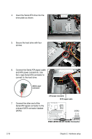
4. Place the ODD side bracket to the ODD, matching the two connectors of the bracket with the holes on the side of the ODD. Bracket connectors ODD side bracket 5. Secure the ODD side bracket to the Serial SATA drive bracket with a screw. 6. Connect the 80-pin IDE cable black connector and 4-pin ATX power connector to the IDE connector and power connector at the rear of the optical disk drive. 2-18 Chapter 2: Hardware setup
-
 1
1 -
2
-
3
-
4
-
5
-
6
-
7
-
8
-
9
-
10
-
11
-
12
-
13
-
14
-
15
-
16
-
17
-
18
-
19
-
20
-
21
-
22
-
23
-
24
-
25
-
26
-
27
-
28
-
29
-
30
-
 31
31 -
 32
32 -
 33
33 -
 34
34 -
 35
35 -
 36
36 -
 37
37 -
 38
38 -
 39
39 -
 40
40 -
 41
41 -
42
-
43
-
44
-
45
-
46
-
47
-
48
-
49
-
50
-
51
-
52
-
53
-
54
-
55
-
56
-
57
-
58
-
59
-
60
-
61
-
62
-
63
-
64
-
65
-
66
-
67
-
68
-
69
-
70
-
71
-
72
-
73
-
74
-
75
-
76
-
77
-
78
-
79
-
80
-
81
-
82
-
83
-
84
-
85
-
86
-
87
-
88
-
89
-
90
-
91
-
92
-
93
-
94
-
95
-
96
-
97
-
98
-
99
-
100
-
101
-
102
-
103
-
104
-
105
-
106
-
107
-
108
-
109
-
110
-
111
-
112
-
113
-
114
-
115
-
116
-
117
-
118
-
119
-
120
-
121
-
122
-
123
-
124
-
125
-
126
-
127
-
128
-
129
-
130
-
131
-
132
-
133
-
134
-
135
-
136
-
137
-
138
-
139
-
140
-
141
-
142
-
143
-
144
-
145
-
146
-
147
-
148
 |
 |

Chapter 2:
Hardware setup
2-18
4.
Place the ODD side bracket to the
ODD, matching the two connectors
of the bracket with the holes on the
side of the ODD.
ODD side bracket
Bracket
connectors
5.
Secure the ODD side bracket to the
Serial SATA drive bracket with a
screw.
6.
Connect the 80-pin IDE cable black
connector and 4-pin ATX power
connector to the IDE connector and
power connector at the rear of the
optical disk drive.