Biostar IDEQ 200A iDEQ 200A user's manual - Page 22
Jusbv1/jusbv2/jusbv3
 |
View all Biostar IDEQ 200A manuals
Add to My Manuals
Save this manual to your list of manuals |
Page 22 highlights
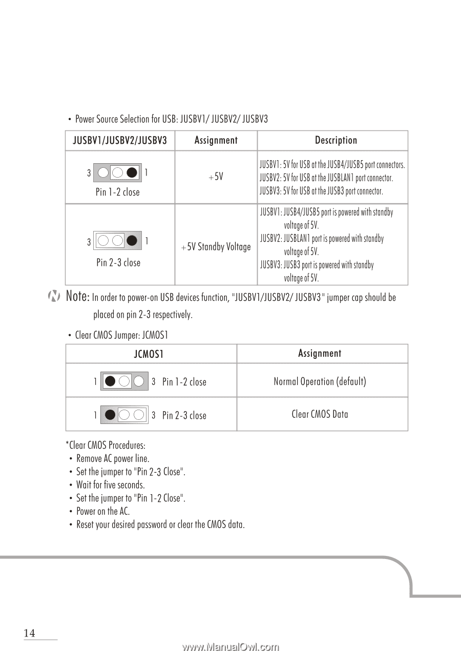
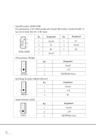
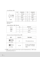
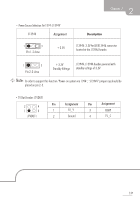
• Power Source Selection for USB: JUSBV1/JUSBV2/JUSBV3 JUSBV1/JUSBV2/JUSBV3 Assignment Description 3 0 00 1 Pin 1-2 close JUSBV1:5Vfor USBattheJUSB4/JUSB5 port connectors. +5V JUSBV2:5Vfor USBattheJUSBLAN1 port connector. JUSBV3:5Vfor USBattheJUSB3 port connector. 3 00 • 1 Pin 2-3 close +5V Standby Voltage JUSBVI:JUSB4/JUSB5portis poweredwith standby voltage of 5V. JUSBV2:JUSBLAN1portis poweredwith standby voltage of 5V. JUSBV3:JUSB3portis poweredwith standby voltage of 5V. (Z) Note: In order to power-on USB devices function, "JUSBV /JUSBV2/JUSBV3" jumper cap should be placed on pin 2-3 respectively. • Clear CMOS Jumper: JCMOS1 JCMOS1 Assignment • 0 0 3 Pin 1-2 close Normal Operation (default) • 00 3 Pin 2-3 close Clear CMOS Data *Clear CMOS Procedures: • Remove AC power line. • Set the jumper to "Pin 2-3 Close". • Wait for five seconds. • Set the jumper to "Pin 1-2 Close". • Power on the AC. • Reset your desired password or clear the CMOS data. 14
-
 1
1 -
2
-
3
-
4
-
5
-
6
-
7
-
8
-
9
-
10
-
11
-
12
-
13
-
14
-
15
-
16
-
 17
17 -
 18
18 -
 19
19 -
 20
20 -
 21
21 -
 22
22 -
 23
23 -
 24
24 -
 25
25 -
 26
26 -
 27
27 -
28
-
29
-
30
-
31
-
32
-
33
-
34
-
35
-
36
-
37
-
38
-
39
-
40
-
41
-
42
-
43
-
44
-
45
-
46
-
47
-
48
-
49
-
50
-
51
-
52
-
53
-
54
-
55
-
56
 |
 |