Biostar M7VKQ M7VKQ user's manual - Page 52
SDRAM Cycle Length, Bank Interleave, Memory Hole, System BIOS Cacheable, Video RAM Cacheable
 |
View all Biostar M7VKQ manuals
Add to My Manuals
Save this manual to your list of manuals |
Page 52 highlights
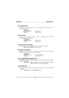
Chapter 2 BIOS Setup SDRAM Cycle Length When synchronous DRAM is installed, the number of clock cycles of CAS latency depends on the DRAM timing. Do not reset this field from the default value specified by the system designer. The Choices: 3 (default), 2. Bank Interleave This item allows you to enable or disable the bank interleave feature. The Choices: Disabled (default), 2Bank, 4Bank. Memory Hole When enabled, you can reserve an area of system memory for ISA adapter ROM. When this area is reserved, it cannot be cached. Refer to the user documentation of the peripheral you are installing for more information. The Choices: Disabled (default), 15M-16M. System BIOS Cacheable When enabled, accesses to system BIOS ROM addressed at F0000H-FFFFFH is cached, provided that the cache controller is enabled. The Choices: Enabled (default), Disabled. Video RAM Cacheable Select Enabled allows caching of the video BIOS, resulting in better system performance. However, if any program writes to this memory area, a system error may result. The Choices: Enabled (default), Disabled. AGP Aperture Size Select the size of the Accelerated Graphics Port (AGP) aperture. The aperture is a portion of the PCI memory address range dedicated for graphics memory address space. Host cycles that hit the aperture range are forwarded to the AGP without any translation. The Choices: 64M (default),256M, 128M, 64M, 32M, 16M, 8M, 4M. AGP Mode This item allows you to select the AGP Mode. The Choices: 4X (default), 2X, 1X. 2-15
-
 1
1 -
2
-
3
-
4
-
5
-
6
-
7
-
8
-
9
-
10
-
11
-
12
-
13
-
14
-
15
-
16
-
17
-
18
-
19
-
20
-
21
-
22
-
23
-
24
-
25
-
26
-
27
-
28
-
29
-
30
-
31
-
32
-
33
-
34
-
35
-
36
-
37
-
38
-
39
-
40
-
41
-
42
-
43
-
44
-
45
-
46
-
 47
47 -
 48
48 -
 49
49 -
 50
50 -
 51
51 -
 52
52 -
 53
53 -
 54
54 -
 55
55 -
 56
56 -
 57
57 -
58
-
59
-
60
-
61
-
62
-
63
-
64
-
65
-
66
-
67
-
68
-
69
-
70
-
71
-
72
-
73
-
74
-
75
-
76
-
77
-
78
 |
 |
