Bose Lifestyle 38 Series IV Installation guide - Page 14
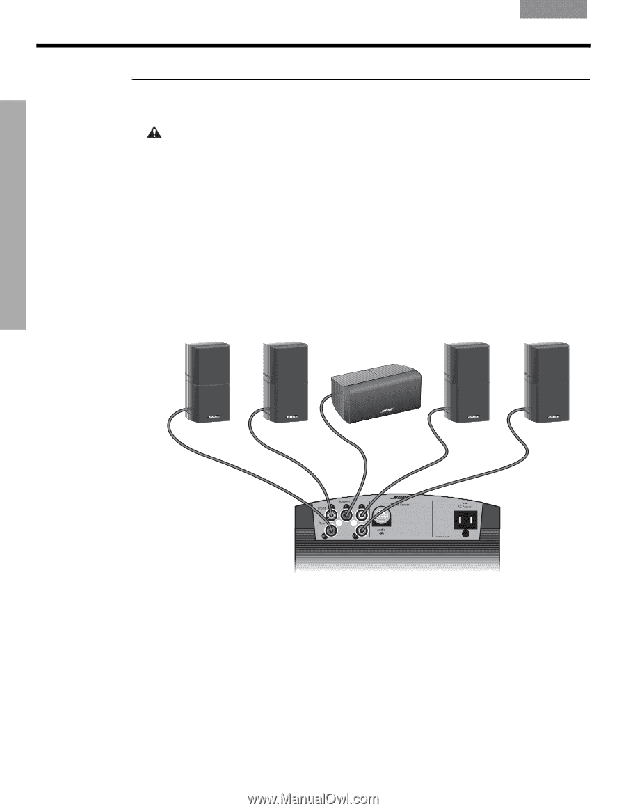
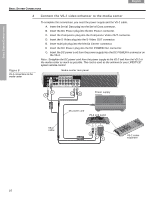
Connect the speaker cables to the module, Front L, Rear LR
 |
View all Bose Lifestyle 38 Series IV manuals
Add to My Manuals
Save this manual to your list of manuals |
Page 14 highlights
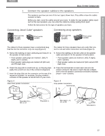
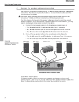
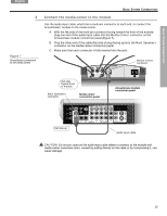
BASIC SYSTEM CONNECTIONS Dansk DEsepuatsñcohl FItralniaçnaois Nederlands Svenska English BASIC SYSTEM CONNECTIONS 2 Figure 6 Speaker connections to the Acoustimass® module Connect the speaker cables to the module You may find it convenient to temporarily turn the module upside down while making these connections. Then, be sure to place the module on its side or bottom surface when the connections are completed. CAUTION: Before you make these connections, be sure that the media center and the Acoustimass® module are NOT yet connected to an AC (mains) power outlet. The RCA plugs on the free end of the speaker cables are colored to match the colored speaker connectors on the Acoustimass connection panel. For a color reference, you may want to use the Quick Setup Guide provided in the carton. A. Connect the front speaker cables to the Acoustimass module (Figure 6): • Plug the white front left (L) cable into the white Front L connector. • Plug the light blue front right (R) cable into the light blue Front R connector. • Plug the brown front center (C) cable into the brown Front C connector. B. Connect the rear speaker cables to the Acoustimass module (Figure 6): • Plug the light green left rear (LR) cable into the light green Rear LR connector. • Plug the purple right rear (RR) cable into the purple Rear RR connector. Right Rear Right Front Center Front Left Front Left Rear RCL RR LR Acoustimass module connector panel If you need longer cables: To lengthen speaker cables, as needed, you can splice in 18-gauge or thicker cord (connecting + to + and - to -). Or, you can order heavy-duty speaker extension cables from Bose. To contact Bose directly, refer to the contact list provided in the carton. 14
-
 1
1 -
2
-
3
-
4
-
5
-
6
-
7
-
8
-
 9
9 -
 10
10 -
 11
11 -
 12
12 -
 13
13 -
 14
14 -
 15
15 -
 16
16 -
 17
17 -
 18
18 -
 19
19 -
20
-
21
-
22
-
23
-
24
-
25
-
26
-
27
-
28
-
29
-
30
-
31
-
32
-
33
-
34
-
35
-
36
-
37
-
38
-
39
-
40
-
41
-
42
-
43
-
44
-
45
-
46
-
47
-
48
-
49
-
50
-
51
-
52
-
53
-
54
-
55
-
56
-
57
-
58
-
59
-
60
-
61
-
62
-
63
-
64
-
65
-
66
-
67
-
68
-
69
-
70
-
71
-
72
-
73
-
74
-
75
-
76
-
77
-
78
-
79
-
80
-
81
-
82
-
83
-
84
-
85
-
86
-
87
-
88
-
89
-
90
-
91
-
92
-
93
-
94
-
95
-
96
-
97
-
98
-
99
-
100
-
101
-
102
-
103
-
104
-
105
-
106
-
107
-
108
-
109
-
110
-
111
-
112
-
113
 |
 |