Brother International BE-1204B Instruction Manual - English - Page 30
Names of Machine Components
 |
View all Brother International BE-1204B manuals
Add to My Manuals
Save this manual to your list of manuals |
Page 30 highlights
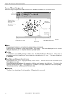
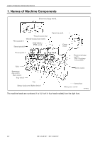
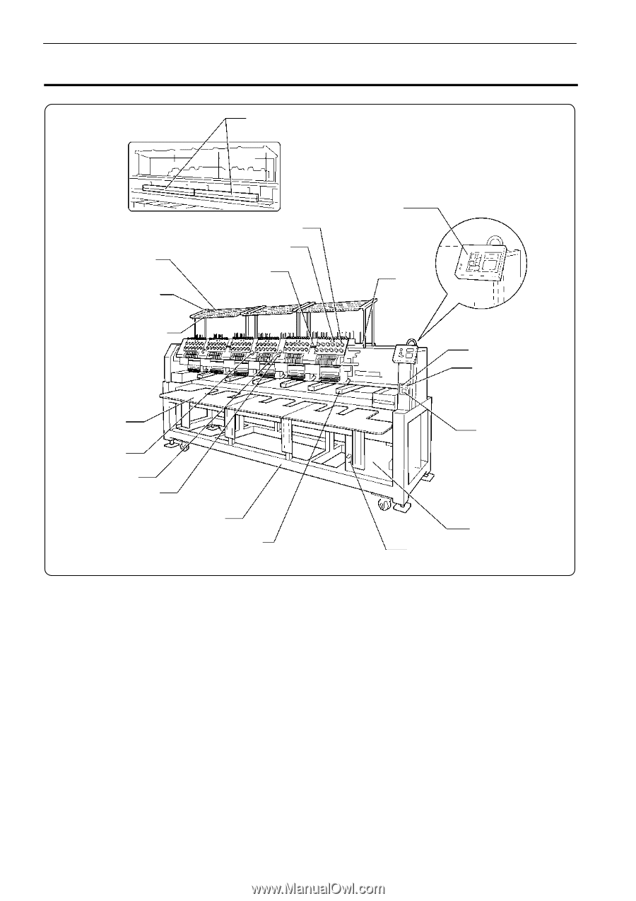
Chapter 2 Preparation of Embroidery Machine 1. Names of Machine Components Fluorescent lamp switch Thread tension dial Thread guide C Thread guide B Thread tension base switch STEP BACK / FWD switch Operation panel Cotton stand Thread guide A Fluorescent lamp switch Flat / Cap hoop select switch Table Emergency stop switch Start switch Stop switch Leg Rotary hook cover (Safety device) Power switch Control box Main power switch W1401Q The machine heads are numbered 1 to 6 (1 to 4 in four head models) from the right front. 2-2 BE-1204B-BC • BE-1206B-BC
-
 1
1 -
2
-
3
-
4
-
5
-
6
-
7
-
8
-
9
-
10
-
11
-
12
-
13
-
14
-
15
-
16
-
17
-
18
-
19
-
20
-
21
-
22
-
23
-
24
-
 25
25 -
 26
26 -
 27
27 -
 28
28 -
 29
29 -
 30
30 -
 31
31 -
 32
32 -
 33
33 -
 34
34 -
 35
35 -
36
-
37
-
38
-
39
-
40
-
41
-
42
-
43
-
44
-
45
-
46
-
47
-
48
-
49
-
50
-
51
-
52
-
53
-
54
-
55
-
56
-
57
-
58
-
59
-
60
-
61
-
62
-
63
-
64
-
65
-
66
-
67
-
68
-
69
-
70
-
71
-
72
-
73
-
74
-
75
-
76
-
77
-
78
-
79
-
80
-
81
-
82
-
83
-
84
-
85
-
86
-
87
-
88
-
89
-
90
-
91
-
92
-
93
-
94
-
95
-
96
-
97
-
98
-
99
-
100
-
101
-
102
-
103
-
104
-
105
-
106
-
107
-
108
-
109
-
110
-
111
-
112
-
113
-
114
-
115
-
116
-
117
-
118
-
119
-
120
-
121
-
122
-
123
-
124
-
125
-
126
-
127
-
128
-
129
-
130
-
131
-
132
-
133
-
134
-
135
-
136
-
137
-
138
-
139
-
140
-
141
-
142
-
143
-
144
-
145
-
146
-
147
-
148
-
149
-
150
-
151
-
152
-
153
-
154
-
155
-
156
-
157
-
158
-
159
-
160
-
161
-
162
-
163
-
164
-
165
-
166
-
167
-
168
-
169
-
170
-
171
-
172
-
173
-
174
-
175
-
176
-
177
-
178
-
179
-
180
-
181
-
182
-
183
-
184
-
185
-
186
-
187
-
188
-
189
-
190
-
191
-
192
-
193
-
194
-
195
-
196
-
197
-
198
-
199
-
200
-
201
-
202
-
203
-
204
-
205
-
206
-
207
-
208
-
209
-
210
-
211
-
212
-
213
-
214
-
215
-
216
-
217
-
218
-
219
-
220
-
221
-
222
-
223
-
224
-
225
-
226
-
227
-
228
-
229
-
230
-
231
-
232
-
233
-
234
-
235
-
236
-
237
-
238
-
239
-
240
-
241
-
242
-
243
-
244
-
245
-
246
-
247
-
248
-
249
-
250
-
251
-
252
-
253
-
254
-
255
-
256
-
257
-
258
-
259
-
260
-
261
-
262
 |
 |
2-2
BE-1204B-BC ° BE-1206B-BC
Chapter 2 Preparation of Embroidery Machine
1. Names of Machine Components
W1401Q
The machine heads are numbered 1 to 6 (1 to 4 in four head models) from the right front.
Fluorescent lamp switch
Operation panel
Thread tension dial
Thread guide C
Thread guide B
Thread guide A
Thread tension base switch
Cotton
stand
Table
Stop switch
Leg
Main power switch
Control box
Power switch
Fluorescent lamp
switch
Flat / Cap hoop
select switch
Emergency
stop switch
STEP BACK /
FWD switch
Start switch
Rotary hook cover (Safety device)