Canon DIGISUPER 80 manual for XJ100x9.3B AF XJ100x9.3B XJ95x12.4B XJ95x8.6B XJ - Page 48
Mounting the, Accessories for Manual, Control System
 |
View all Canon DIGISUPER 80 manuals
Add to My Manuals
Save this manual to your list of manuals |
Page 48 highlights
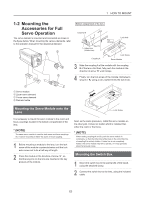
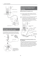
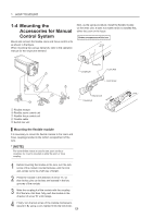
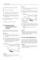
1 HOW TO MOUNT 1-4 Mounting the Accessories for Manual Control System Mount and connect the flexible zoom and focus control units as shown in the figure. When mounting the various demands, refer to the operation manual for the respective demand. Next, as the same procedure, install the flexible module on the other joint. It does not matter which is installed first, either the zoom or the focus. Bottom compartment of the lens Arrow A Key Pin Coupling B Lock Axis Lock Screw Key Groove Coupling A Arrow B Lock ᶃ Flexible module ᶄ Flexible zoom control unit ᶅ Flexible focus control unit ᶆ Flexible cable ᶇ Switch box unit Mounting the flexible module It is necessary to mount the flexible module to the zoom and focus couplings located in the bottom compartment of the lens. * (NOTE) The same flexible module is used for both zoom and focus couplings. So, it can be mounted on either the zoom or focus coupling. 1 Before mounting the module to the lens, turn the lock screw of the module counterclockwise until the lock axis comes out to its a half way of length. 2 Press the module in the direction of arrow "A", so that the key pins on the lens are inserted in the key grooves of the module. 3 Mate the coupling A of the module with the coupling B of the lens. And then, fully push the module in the direction of arrow "B" until it stops. 4 Finally, turn the lock screw of the module clockwise to secure it. By using a coin, tighten firmly the lock knob. E6
-
 1
1 -
2
-
3
-
4
-
5
-
6
-
7
-
8
-
9
-
10
-
11
-
12
-
13
-
14
-
15
-
16
-
17
-
18
-
19
-
20
-
21
-
22
-
23
-
24
-
25
-
26
-
27
-
28
-
29
-
30
-
31
-
32
-
33
-
34
-
35
-
36
-
37
-
38
-
39
-
40
-
41
-
42
-
 43
43 -
 44
44 -
 45
45 -
 46
46 -
 47
47 -
 48
48 -
 49
49 -
 50
50 -
 51
51 -
 52
52 -
 53
53 -
54
-
55
-
56
-
57
-
58
-
59
-
60
-
61
-
62
-
63
-
64
-
65
-
66
-
67
-
68
-
69
-
70
-
71
-
72
-
73
-
74
-
75
-
76
-
77
-
78
-
79
-
80
-
81
-
82
-
83
-
84
-
85
-
86
-
87
-
88
-
89
-
90
-
91
-
92
-
93
-
94
-
95
-
96
-
97
-
98
-
99
-
100
-
101
-
102
-
103
-
104
-
105
-
106
-
107
-
108
-
109
-
110
-
111
-
112
-
113
-
114
-
115
-
116
-
117
-
118
-
119
-
120
-
121
-
122
-
123
-
124
-
125
-
126
-
127
-
128
-
129
-
130
-
131
-
132
-
133
-
134
-
135
-
136
 |
 |
