Canon DIGISUPER 80 manual for XJ100x9.3B AF XJ100x9.3B XJ95x12.4B XJ95x8.6B XJ - Page 52
Iris Mode Setting
 |
View all Canon DIGISUPER 80 manuals
Add to My Manuals
Save this manual to your list of manuals |
Page 52 highlights
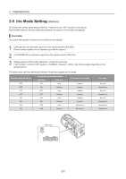
2 PREPARATION 2-5 Iris Mode Setting (Option) DIP switch (iris control select switch) SW2 No. 4 was set to the "OFF" position at the factory. See the table below to find the relationship between the position of the switch and signals. Iris mode Iris control and operation depend on the following three signals 1 Enforced auto iris command signal from the camera system (IRIS ENF) (Some camera models are not capable to provide this signal.) 2 AUTO/REMOTE iris command signal from the camera system (IRIS A/R) 3 Setting position of DIP switch (SW2) No. 4 inside the lens body ("ON" position: I.LOCAL/"OFF" position: I.CAMERA However, I.LOCAL may not be usable depending on the specifications.) The table below lists the relationship between these three signals and iris mode. Position of the DIP switch OFF OFF OFF OFF ON ON ON ON Command signal from camera IRIS ENF IRIS A/R ON Auto ON Remote OFF Auto OFF Remote ON Auto ON Remote OFF Auto OFF Remote Iris Control signal from Camera Camera Camera Camera Camera Camera Switch box Switch box Iris mode Auto iris Remote iris Auto iris Remote iris Auto iris Remote iris Remote iris Remote iris DIP switch E10
-
 1
1 -
2
-
3
-
4
-
5
-
6
-
7
-
8
-
9
-
10
-
11
-
12
-
13
-
14
-
15
-
16
-
17
-
18
-
19
-
20
-
21
-
22
-
23
-
24
-
25
-
26
-
27
-
28
-
29
-
30
-
31
-
32
-
33
-
34
-
35
-
36
-
37
-
38
-
39
-
40
-
41
-
42
-
43
-
44
-
45
-
46
-
 47
47 -
 48
48 -
 49
49 -
 50
50 -
 51
51 -
 52
52 -
 53
53 -
 54
54 -
 55
55 -
 56
56 -
 57
57 -
58
-
59
-
60
-
61
-
62
-
63
-
64
-
65
-
66
-
67
-
68
-
69
-
70
-
71
-
72
-
73
-
74
-
75
-
76
-
77
-
78
-
79
-
80
-
81
-
82
-
83
-
84
-
85
-
86
-
87
-
88
-
89
-
90
-
91
-
92
-
93
-
94
-
95
-
96
-
97
-
98
-
99
-
100
-
101
-
102
-
103
-
104
-
105
-
106
-
107
-
108
-
109
-
110
-
111
-
112
-
113
-
114
-
115
-
116
-
117
-
118
-
119
-
120
-
121
-
122
-
123
-
124
-
125
-
126
-
127
-
128
-
129
-
130
-
131
-
132
-
133
-
134
-
135
-
136
 |
 |
