Canon PIXMA iP4200 Service Manual - Page 18
Purge unit: QM2
 |
View all Canon PIXMA iP4200 manuals
Add to My Manuals
Save this manual to your list of manuals |
Page 18 highlights
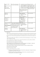
Purge unit: QM22208 secure the waste ink tube to the waste ink tube holder. Waste ink tube: QC16458 Waste ink tube holder: QC1-6460 1. To protect the waste ink case unit, the tube tube from being pinched conditions are not visible. when reassembling the For confirmation of the printer unit chassis into tube conditions, perform the bottom case unit, tape the manual purging 3 or 4 the tube (at 2 locations). times, and confirm that no [See 3-2. Special Notes on strange noise is heard. Repair Servicing, (3) Printer unit and bottom case unit assembly.] Platen unit QM2-2202 PR lift shaft ass'y QL2-0936 CL input gear QC1-6213 Timing slit strip film QC1-6394 Timing slit disk film QC1-6229 After replacement: 1. Check the ink system function. [See 3-3. Adjustment / Settings, (5) Service mode.] At replacement: 1. Apply grease to the sliding portions. [See 3.3. Adjustment / Settings, (2) Grease application.] - Upon contact with the film, After replacement: wipe the film with ethanol. 1. Perform the print head - Confirm no grease is on the alignment in the user film. (Wipe off any grease mode. thoroughly with ethanol.) - Do not bend the film - Service test print - Service test print - Service test print Print head QY6-0059 After replacement: 1. Perform the print head alignment in the user mode. - Service test print *1: General notes: - Make sure that the flexible cables and wires in the harness are in the proper position and connected correctly. [See 3-2. Special Notes on Repair Servicing, (2) Flexible cable and harness wiring, connection, for details.] - Protect the waste ink tube from being pinched when assembling the printer unit chassis into the bottom case unit. Since the tube conditions after assembly are not visible, perform the manual purging 3 or 4 times to confirm that no strange noise is heard. [See 3-2. Special Notes on Repair Servicing, (3) Printer unit and bottom case unit assembly, for details.] - Do not drop the ferrite core, which may cause damage. - Protect electrical parts from damage due to static electricity. - Before removing a unit, after removing the power cord, allow the printer to sit for approx. 1 minute (for capacitor discharging to protect the logic board ass'y from damages). - Do not touch the timing slit strip film and timing slit disk film. No grease or abrasion is allowed. - Protect the units from soiled with ink. - Protect the housing from scratches. - Exercise caution with the red screws, as follows: i. The red screws of the paper feed motor may be loosened only at replacement of the paper feed motor unit (DO NOT loosen them in other cases). ii. DO NOT loosen the red screws on both sides of the main chassis, securing the carriage shaft positioning (they are not adjustable in servicing). 1-13
-
 1
1 -
2
-
3
-
4
-
5
-
6
-
7
-
8
-
9
-
10
-
11
-
12
-
 13
13 -
 14
14 -
 15
15 -
 16
16 -
 17
17 -
 18
18 -
 19
19 -
 20
20 -
 21
21 -
 22
22 -
 23
23 -
24
-
25
-
26
-
27
-
28
-
29
-
30
-
31
-
32
-
33
-
34
-
35
-
36
-
37
-
38
-
39
-
40
-
41
-
42
-
43
-
44
-
45
-
46
-
47
-
48
-
49
-
50
-
51
-
52
-
53
-
54
-
55
-
56
-
57
 |
 |
