Cub Cadet CC 600 Operation Manual - Page 8
Adjustments, Set-Up
 |
View all Cub Cadet CC 600 manuals
Add to My Manuals
Save this manual to your list of manuals |
Page 8 highlights
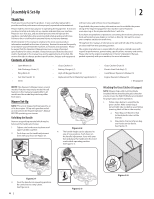
Attaching Side Discharge Chute Your mower is shipped as a mulcher. To convert to side discharge, make sure grass catcher is off the unit and mower rear discharge door is closed. 1. On the side of the mower deck, lift the mulch plug. See Figure 2-13. Adjustments Cutting Height (Standard Wheel) There is a cutting height adjustment lever located above the rear left wheel. See Figure 2-15. The casters can be locked in a straight ahead position or positioned to swivel freely. See Figure 2-17. Deck Stud Mulch Plug Figure 2-13 2. Slide two hooks of side discharge chute under hinge pin on mulch plug assembly and position hole in the chute over and on to the deck stud located behind the discharge opening. See Figure 2-13. Lower mulch plug. 3. Secure the chute to the mowing deck using the wing knob included in the manual bag. Hand tighten the wing knob onto the deck stud. See Figure 2-14. Figure 2-15 1. Pull lever out and away from mower. 2. Move lever forward or back for desired cutting height. 3. Release lever towards mower deck. NOTE: On the standard wheel units, this lever adjusts the rear and front wheel height simultaneously. On caster wheel models, it adjusts the rear wheel height only. Cutting Height (Caster Wheel) If equipped, the caster wheels cutting height are determined by selecting one of six positions on each caster assembly. Refer to Figure 2-16. Figure 2-17 1. Lift lock pins. 2. Place in larger holes to lock wheels. Place pins in smaller holes to allow casters to rotate freely for turning. Set-Up Electric Starter (If Equipped) NOTE: Remove cable tie (a) from around battery box. Cable tie is used for shipping only. See Figure 2-18. (a) (a) Figure 2-14 NOTE: Do not remove side mulch plug at any time. (b) Figure 2-16 1. Remove wing nut (a) from axle bolt (b). Slide axle bolt from the assembly and select a cutting height. 2. Reinsert axle bolt in the square hole desired through wheel assembly and secure with wing nut removed in Step 1. IMPORTANT: All wheels must be placed in the same relative position. For rough or uneven lawns, move the height adjustment lever to a higher position. This will stop scalping of grass. Figure 2-18 Gas and Oil Fill-Up Refer to the Engine Operator's Manual for additional engine information. 1. Add provided oil before starting unit for the first time. 2. Service the engine with gasoline as instructed in the Engine Operator's Manual. WARNING: Use extreme care when handling gasoline. Gasoline is extremely flammable and the vapors are explosive. Never fuel the machine indoors or while the engine is hot or running. Extinguish cigarettes, cigars, pipes and other sources of ignition. 8 Section 2 - Assembly & Set-Up
-
 1
1 -
2
-
 3
3 -
 4
4 -
 5
5 -
 6
6 -
 7
7 -
 8
8 -
 9
9 -
 10
10 -
 11
11 -
 12
12 -
 13
13 -
14
-
15
-
16
-
17
-
18
-
19
-
20
-
21
-
22
-
23
-
24
-
25
-
26
-
27
-
28
-
29
-
30
-
31
-
32
 |
 |
