Dacor HGPR30 Installation Instruction - 30" Pro Gas Range - Page 6
Cabinet Layout
 |
View all Dacor HGPR30 manuals
Add to My Manuals
Save this manual to your list of manuals |
Page 6 highlights
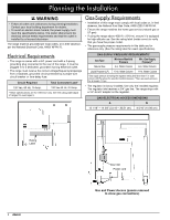
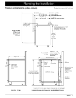
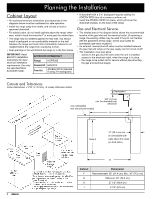
Planning the Installation Cabinet Layout • All maximum/minimum dimensions and clearances in the diagrams below must be maintained for safe operation. • Install the range away from drafts, and include a hood or approved downdraft. • For safety's sake, do not install cabinets above the range; otherwise, install a hood that extends 5" or more past the cabinet face. • The range may be installed against the rear wall. You should install a backguard or non-combustible material on the wall between the range and hood. Non-combustible material is not needed behind the range from countertop to floor. • Seal openings in the wall behind the range or in the floor below. IMPORTANT: Read ERV3015 Installation Instructions for duct/ electrical installation requirements. Use only the specified Dacor downdraft model. APPROVED DOWNDRAFT Range HGPR30S Downdraft ERV3015 Trim Kit ATKERV-RP30 (Needed if using 3-in backguard) • A downdraft with a 3-in. backguard requires adding the ATKERV-RP30 trim kit to create a uniform unit. • Install the ATKERV-RP30 trim piece, which will cover the downdraft chassis, on the back of the range. Gas and Electrical Service • The shaded area in the diagram below shows the recommended location of the gas inlet and the electrical outlet. (If replacing a range, the existing utilities may be used if they do not interfere with the placement of this range. Check local codes for permissible gas-valve locations.) • An external, manual shut-off valve must be installed between the gas inlet and range so the gas supply can be turned on/off • The installation must also allow: -- access to the gas shut-off valve when the unit is installed. -- access to the electrical outlet, when the range is in place. -- the range to be pulled out for service without disconnecting the gas and electrical supply. Cutouts and Tolerances Cutout tolerances: +1/16" (+1.6 mm), -0 unless otherwise stated Backsplash IJ 3/8" (1.0 cm) min. for downdraft cap non-combustible clearance rear wall (recommended) H Note 2 10" (25.4 cm) min. to combustible side walls above the range (on both sides) G Callout F G H I Dimension Recommended: 36" (91.4 cm); Min.: 30" (76.2 cm) Minimum: 30" (76.2 cm) 27 1/2" (69.9 cm) 3 1/2" (8.9 cm) 4
-
 1
1 -
 2
2 -
 3
3 -
 4
4 -
 5
5 -
 6
6 -
 7
7 -
 8
8 -
 9
9 -
 10
10 -
 11
11 -
 12
12 -
13
-
14
-
15
-
16
 |
 |
