Dacor HGPR30 Installation Instruction - 30" Pro Gas Range - Page 8
Wall-Mounting the Anti-Tip Bracket
 |
View all Dacor HGPR30 manuals
Add to My Manuals
Save this manual to your list of manuals |
Page 8 highlights
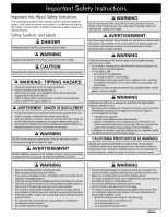
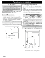
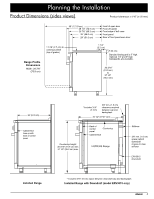
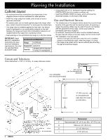
Installation Instructions Screws Attaching the Bracket to a Wood Floor If hard flooring covers the wood, drill pilot holes to expose the wood below, then drill the mounting holes. Use the right drill bit for the surface. Having drilled the pilot holes: 1. Drill 4 mounting holes into the wood with a 1/16" drill bit (for #8 screws) or a 1/8" bit (for #12 screws). 2. Position the anti-tip bracket holes over the holes in the floor. 3. Thread the screws into the wood, and tighten them. Bracket Install Detail Plastic Anchors Mounting Holes 10 7/8" A 22 1/2" B Range center line CL Wall-Mounting the Anti-Tip Bracket • To use this option: -- the range's front panel (exterior surface of the door-not the forward edge of the bull nose) must be 27 in. (68.6 cm) or less from the wall behind the range. -- the bracket screws must be able to thread into the wall's base plate (see the graphic, Step 5, Pg. 7). • Notches on the bracket sides indicate the minimum required height of the base plate and that any floor covering does not keep screw threads from engaging the base plate. Using the graphic in Step 4 and the final installation cabinet/cutout dimensions, find the range's center line and front panel location. 1. Determine and mark the position of the anti-tip bracket. 2. Place the bracket in position. 3. Mark a dot at the notch on each side of the bracket. Range front panel* Bracket Placement 1. Determine the installed range's center line and position of the front panel based on the Product Dimensions (Pg. 3) and the actual cabinet/cutout dimensions used for the installation. 2. Using the previous diagrams, determine placement of the antitip bracket. Pencil the four mounting-hole locations on the floor. 3. Determine the screw size. Minimum full thread depth (portion of screw threaded into wood/slab) for wood is 3/8" (1 cm) and for concreter is 5/8" (1.6 cm). See SCREW SIZE TABLE (Pg. 7) to select the correct screw size. 4. Drill just deep enough to see if the bit contacts the base plate. -- If the bit contacts the base plate, wall mounting is suitable. -- If the bit does not contact the base plate, you must either floor-mount the bracket.) Attaching the Bracket to a Concrete Floor 1. Through existing flooring, drill four 3/8" diameter countersink holes to (but not into) the concrete slab. 2. With a masonry bit, drill four anchor holes 1-1/4" (3.2 cm) into the concrete slab using a 3/16" drill bit. This depth is longer than the anchor but needed for proper installation. 3. Clear the holes of dust and debris. 4. With a hammer, tap an anchor into each hole so the anchor top is flush with the slab surface. 5. Align the bracket holes with the anchor holes. 6. Thread and tighten the screws into the anchors. Range front panel CL CL 11 7/8" 6
-
 1
1 -
2
-
 3
3 -
 4
4 -
 5
5 -
 6
6 -
 7
7 -
 8
8 -
 9
9 -
 10
10 -
 11
11 -
 12
12 -
 13
13 -
14
-
15
-
16
 |
 |
