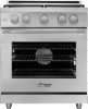
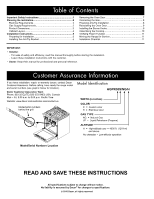
Dacor HGPR30 Installation Instruction - 30" Pro Gas Range - Page 7
Installation Instructions
 |
View all Dacor HGPR30 manuals
Add to My Manuals
Save this manual to your list of manuals |
Page 7 highlights
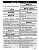
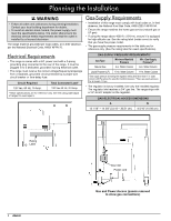
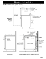
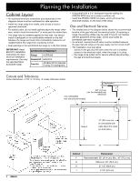
Installation Instructions Preparing for Installation WARNING • If the home utilities do not meet product specifications, delay the installation until the proper services are installed by qualified personnel. • Install the anti-tip bracket before you install the range. IMPORTANT: Within the Commonwealth of Massachusetts, this appliance must be installed by a licensed plumber or gas fitter. Installing Rear Trim If installing the range in the self-rimming configuration, or if the range will be used with a downdraft, install the rear trim piece first. Remove the existing screws that hold the backguard in place and use them to attach the trim piece. Unpacking the Range Unpack the parts box, and verify that all required parts are present. If anything is absent or damaged, contact your dealer immediately. Do not install a damaged or incomplete range. Parts List - Grates (2) - Standard burner caps (3 brass, 3 porcelain)* - Standard burner rings (3) - SimmerSear burner caps (1 brass, 1 porcelain)* - SimmerSear burner ring (1) - SimmerSear burner head (1) - GlideRack™ oven racks (2) - Standard rack (1) - 5 Knobs (2 MAX GRIDDLE, 2 Standard, 1 Oven) - Anti-tip bracket with screws and anchors - Griddle (1) - Wok ring (1) - Broiler pan/grill (1) - Stainless steel cleaner (1) - Literature kit (1) *The range comes with two styles of burner caps (brass and porcelain) to suit owner preference. (Brass burner caps discolor with use; this does not affect function.) Replacing the Backguard If a different backguard will be used, please assemble it before pushing the range into position. Model No. APB30GLP APB30D9 Item 1.5-inch high Backguard (Low Profile) 9-inch high Backguard Downdraft Installation If installing a downdraft, install it before moving the range into position. An additional trim kit must be used to unify the range, downdraft, and backguard. Model No. ERV3015 ATKERV-RP30 Item Downdraft Trim Kit Installing the Anti-Tip Bracket The anti-tip bracket (see the parts box), can be installed one of two ways: • Floor mounting (preferred). • Wall mounting (if floor mounting is unsuitable). If the front panel of the range (excluding bull nose) is more than 27 inches (68.6 cm) from the back wall, or if the flooring is too thick (see Installing the Anti-Tip Bracket on the Wall), use the wall mounting method. Floor-Mounting the Anti-Tip Bracket Concrete anchors shown. Do not use anchors on a wooden sub-floor. Anti-tip Bracket Floor surface Sub-floor WARNING The anti-tip bracket must be attached as instructed to the concrete slab or wood sub-floor under any flooring type (including cement board). Do not attach the anti-tip bracket directly to floor coverings Use the anchors and 4 of the Phillips-head screws when attaching the anti-tip bracket to a concrete sub-floor. Do not use anchors when attaching the bracket to a wooden sub-floor. • Plastic anchors (4) • 1-in. #8 (4) • 1 1/4-in. #8 (4) • 1 3/4-in. #12 (4) 5
-
 1
1 -
 2
2 -
 3
3 -
 4
4 -
 5
5 -
 6
6 -
 7
7 -
 8
8 -
 9
9 -
 10
10 -
 11
11 -
 12
12 -
13
-
14
-
15
-
16
 |
 |
