Dell Alienware m15 R3 Service Manual
Dell Alienware m15 R3 Manual
 |
View all Dell Alienware m15 R3 manuals
Add to My Manuals
Save this manual to your list of manuals |
Dell Alienware m15 R3 manual content summary:
- Dell Alienware m15 R3 | Service Manual - Page 1
Alienware m15 R3 Service Manual Regulatory Model: P87F Regulatory Type: P87F002 June 2020 Rev. A00 - Dell Alienware m15 R3 | Service Manual - Page 2
of data and tells you how to avoid the problem. WARNING: A WARNING indicates a potential for property damage, personal injury, or death. © 2020 Dell Inc. or its subsidiaries. All rights reserved. Dell, EMC, and other trademarks are trademarks of Dell Inc. or its subsidiaries. Other trademarks may be - Dell Alienware m15 R3 | Service Manual - Page 3
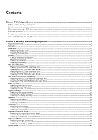
your computer...6 Safety instructions...6 Electrostatic discharge-ESD protection...7 ESD field service kit ...7 Transporting sensitive 10 Installing the base cover...13 Battery...15 Lithium-ion battery precautions...15 Removing the battery...15 Installing the battery...16 M.2 solid-state drive...17 - Dell Alienware m15 R3 | Service Manual - Page 4
...76 Deleting or changing an existing system setup password 76 Clearing CMOS settings...77 Clearing BIOS (System Setup) and System passwords 77 Chapter 5: Troubleshooting...78 Recovering the operating system...78 System diagnostic lights...78 Flea power release...79 WiFi power cycle...79 4 - Dell Alienware m15 R3 | Service Manual - Page 5
Chapter 6: Getting help...80 Contacting Dell...80 5 - Dell Alienware m15 R3 | Service Manual - Page 6
and the contacts. CAUTION: You should only perform troubleshooting and repairs as authorized or directed by the Dell technical assistance team. Damage due to servicing that is not authorized by Dell is not covered by your warranty. See the safety instructions that is shipped with the product or at - Dell Alienware m15 R3 | Service Manual - Page 7
obvious, such as intermittent problems or a shortened product life span. As the industry pushes difficult type of damage to recognize and troubleshoot is the intermittent (also called latent or the hardware is known as bonding. Use only Field Service kits with a wrist strap, mat, and bonding wire - Dell Alienware m15 R3 | Service Manual - Page 8
for safe transport. ESD protection summary It is recommended that all field service technicians use the traditional wired ESD grounding wrist strap and protective anti-static mat at all times when servicing Dell products. In addition, it is critical that technicians keep sensitive parts separate - Dell Alienware m15 R3 | Service Manual - Page 9
with the configuration ordered. Table 1. Screw list Component Base cover Secured to Palm-rest assembly Screw type M2x5 Quantity 2 Screw image Battery Battery M.2 2230 solid-state drive M.2 2230 mounting bracket M.2 2280 solid-state drive M.2 2230 WWAN/ solid-state drive Rear I/O-cover Rear - Dell Alienware m15 R3 | Service Manual - Page 10
Table 1. Screw list (continued) Component Secured to Keyboard-controller board Palm-rest assembly Right I/O-board cable • System board • Right I/O-board Right I/O-board Palm-rest assembly M.2 solid-state drive (SSD) frame Fan and heat-sink assembly Fan and heat-sink assembly System board - Dell Alienware m15 R3 | Service Manual - Page 11
11 - Dell Alienware m15 R3 | Service Manual - Page 12
Steps 1. Remove the two screws (M2x5) that secure the base cover to the palm-rest assembly. 12 - Dell Alienware m15 R3 | Service Manual - Page 13
open the base cover. 4. Lift and slide the base cover off the palm-rest assembly. 5. Disconnect the battery cable from the system board. 6. Peel the tape that secures the battery cable to the battery. 7. Press and hold the power button for five seconds to ground the computer and drain the flea power - Dell Alienware m15 R3 | Service Manual - Page 14
14 - Dell Alienware m15 R3 | Service Manual - Page 15
, do not try to release it as puncturing, bending, or crushing a lithium-ion battery can be dangerous. In such an instance, contact Dell technical support for assistance. See www.dell.com/contactdell. • Always purchase genuine batteries from www.dell.com or authorized Dell partners and resellers - Dell Alienware m15 R3 | Service Manual - Page 16
to the palm-rest assembly. 3. Remove the four screws (M2x3) that secure the battery to the palm-rest assembly. 4. Remove the battery from the palm-rest assembly. Installing the battery Prerequisites If you are replacing a component, remove the existing component before performing the installation - Dell Alienware m15 R3 | Service Manual - Page 17
to the screw holes on the palm-rest assembly. 3. Replace the four screws (M2x4) that secure the battery to the palm-rest assembly. 4. Replace the four screws (M2x3) that secure the battery to the palm-rest assembly. Next steps 1. Install the base cover. 2. Follow the procedure in After working - Dell Alienware m15 R3 | Service Manual - Page 18
18 - Dell Alienware m15 R3 | Service Manual - Page 19
Steps 1. Remove the screw (M2x2.5) that secures the M.2 thermal shield to the M.2 2230 mounting bracket. 2. Remove the M.2 2230 thermal shield from the M.2 2230 solid-state drive. 3. Lift and remove the M.2 2230 solid-state drive from the M.2 card slot on the system board. 4. Remove the screw (M2x2 - Dell Alienware m15 R3 | Service Manual - Page 20
20 - Dell Alienware m15 R3 | Service Manual - Page 21
Steps 1. Place the M.2 2230 mounting bracket on the palm-rest assembly. 2. Align the screw hole on the M.2 2230 mounting bracket to the screw hole on the palm-rest assembly. 3. Replace the screw (M2x2.5) that secures the M.2 2230 mounting bracket to the palm-rest assembly. 4. Align the notch on the - Dell Alienware m15 R3 | Service Manual - Page 22
About this task NOTE: This procedure applies only to computers shipped with a M.2 2280 solid-state drive installed in the following M.2 card slots: • M.2 card slot 1 • M.2 card slot 2 The following image(s) indicate the location of the M.2 2280 solid-state drive and provides a visual representation - Dell Alienware m15 R3 | Service Manual - Page 23
2. Lift and remove the M.2 2280 thermal shield off the M.2 2280 solid-state drive. 3. Slide and remove the M.2 2280 solid-state drive from the M.2 card slot on the system board. Installing the M.2 2280 solid-state drive Prerequisites If you are replacing a component, remove the existing component - Dell Alienware m15 R3 | Service Manual - Page 24
Steps 1. Align the notch on the M.2 2280 solid-state drive with the tab on the M.2 card slot on the system board. 2. Slide the M.2 2280 solid-state drive into the M.2 card slot on the system board. 3. Slide the M.2 2280 thermal shield into the slot on the M.2 SSD frame. 4. Align the screw hole on - Dell Alienware m15 R3 | Service Manual - Page 25
Steps 1. Remove the screw (M2x2.5) that secures the M.2 2230 thermal shield to the left I/O-board. 2. Remove the M.2 2230 thermal shield from the M.2 2230 WWAN/solid-state drive. 3. Lift and remove the M.2 2230 WWAN/solid-state drive from the M.2 card slot on the left I/O-board. Installing the M.2 - Dell Alienware m15 R3 | Service Manual - Page 26
Steps 1. Align the notch on the M.2 2230 WWAN/solid-state drive with the tab on the M.2 card slot on the left I/O-board. 2. Slide the M.2 2230 WWAN/solid-state drive into the M.2 card slot on the left I/O-board. 3. Place the M.2 2230 thermal shield on the M.2 2230 WWAN/solid-state drive. 4. Align - Dell Alienware m15 R3 | Service Manual - Page 27
Steps 1. Peel and lift the Mylar covering the system board. 2. Disconnect and peel the Tron light cable from the system board. NOTE: To prevent damaging your computer ensure the Tron light cable has been disconnected from the system board before removing the rear I/O-cover. 27 - Dell Alienware m15 R3 | Service Manual - Page 28
. 5. Firmly grasp the sides of your computer with both hands and push the rubber feet on the rear I/O-cover outwards with your thumbs to release the rear I/O-cover from the palm-rest assembly. 6. Lift the rear I/O-cover from the palm-rest assembly. Installing the rear I/O-cover Prerequisites If you - Dell Alienware m15 R3 | Service Manual - Page 29
Steps 1. Push the rear I/O-cover into the palm-rest assembly snapping it into place. NOTE: To avoiding damaging your computer, ensure the Tron light cable is not pinched and that the Mylar is pasted on the system board before snapping the rear I/O-cover into place. 2. Replace the two screws (M2.5x4) - Dell Alienware m15 R3 | Service Manual - Page 30
2. Remove the base cover. 3. Remove the rear IO-cover. About this task The following image(s) indicate the location of the display assembly and provides a visual representation of the removal procedure. 30 - Dell Alienware m15 R3 | Service Manual - Page 31
from the wireless card. 5. Peel the tapes securing the antenna cables to system board and left fan. 6. Remove the antenna cables from the routing guides on the left fan and system board. 7. Lift the latch and disconnect the display cable from the connector on the system board. NOTE: Ensure that - Dell Alienware m15 R3 | Service Manual - Page 32
• Antenna cables 12. Remove the eight screws (M2.5x4) securing the display assembly to the palm-rest assembly. 13. Lift the display assembly off the palm-rest assembly. 14. After performing the steps above you are left with the display assembly. Installing the display assembly Prerequisites If you - Dell Alienware m15 R3 | Service Manual - Page 33
33 - Dell Alienware m15 R3 | Service Manual - Page 34
the eight screws (M2.5x4) that secure the display assembly to the palm-rest assembly. 5. Route the following cables to the routing guides on the palm-rest assembly. • Display cable • G-sensor cable • Tobii eye tracker cable (optional) • Antenna cables 6. Place the computer face down. 7. Connect - Dell Alienware m15 R3 | Service Manual - Page 35
the latch. 10. Route the antenna cables to the routing guides on the left fan and system board. 11. Adhere the antenna-cable color scheme for the wireless card supported by your computer. Table 2. Antenna-cable Remove the base cover. 3. Remove the battery. About this task The following image(s) - Dell Alienware m15 R3 | Service Manual - Page 36
speaker cable from the right I/O-board. 2. Lift the right speaker off the palm-rest assembly. 3. Remove the speaker cables from the routing guides on the palm-rest assembly. 4. Lift the left speaker off the palm-rest assembly. Installing the speakers Prerequisites If you are replacing a component - Dell Alienware m15 R3 | Service Manual - Page 37
rubber grommets on the speaker. 2. Route the speaker cable through the routing guides on the palm-rest assembly. 3. Using the alignment posts, place the right the speaker cable to the right I/O-board. Next steps 1. Install the battery. 2. Install the base cover. 3. Follow the procedure in After - Dell Alienware m15 R3 | Service Manual - Page 38
Steps 1. Open the latch and disconnect the keyboard-controller board-cable from keyboard-controller board. 2. Lift the keyboard-controller board-cable off the palm-rest assembly. 3. Open the latch and disconnect the keyboard cable from the keyboard-controller board. 4. Fold up the keyboard cable. 5. - Dell Alienware m15 R3 | Service Manual - Page 39
the latch. 6. Connect the keyboard-controller board cable to the keyboard-controller board and close the latch. Next steps 1. Install the battery. 2. Install the base cover. 3. Follow the procedure in After working inside your computer. Keyboard-controller board Removing the keyboard-controller - Dell Alienware m15 R3 | Service Manual - Page 40
board. 4. Remove the two screws (M2x1.9) that secure the keyboard-controller board to the palm-rest assembly. 5. Pull on the securing tab to release the keyboard-controls board from the palm-rest assembly. 6. Using the plastic tab, pry and remove the keyboard-controller board from the palm-rest - Dell Alienware m15 R3 | Service Manual - Page 41
I/O-board Removing the right I/O-board Prerequisites 1. Follow the procedure in Before working inside your computer. 2. Remove the base cover. 3. Remove the battery. 4. Remove the M.2 2230 solid-state drive. (if it is installed in the right M.2 slot) 5. Remove the M.2 2280 solid-state drive. (if - Dell Alienware m15 R3 | Service Manual - Page 42
Steps 1. Peel and lift the Mylar covering the system board. 2. Disconnect the speaker cable from the right I/O-board. 3. Remove the two screws (M2x3) that secure the right I/O-board cable connecting the right I/O-board and the system board. 4. Lift the right I/O-board cable off the right I/O-board - Dell Alienware m15 R3 | Service Manual - Page 43
M.2 2230 solid-state drive. (if it was the right M.2 slot) 2. Install the M.2 2280 solid-state drive. (if it was in the right M.2 slot) 3. Install the battery. 4. Install the base cover. 5. Follow the procedure in After working inside your computer. 43 - Dell Alienware m15 R3 | Service Manual - Page 44
Removing the system board Prerequisites 1. Follow the procedure in Before working inside your computer. 2. Remove the base cover. 3. Remove the battery. 4. Remove the M.2 2230 solid-state drive. (if applicable) 5. Remove the M.2 2280 solid-state drive. (if applicable) 6. Remove the M.2 2230 WWAN - Dell Alienware m15 R3 | Service Manual - Page 45
Steps 1. Peel the Mylar covering the system board. 2. Remove the screw (M2x3) that secures the wireless card bracket to the left I/O-board. 3. Lift the wireless-card bracket off the left I/O-board. 4. Disconnect the antenna cables from the wireless card on the left I/O-board. 5. Peel the tapes - Dell Alienware m15 R3 | Service Manual - Page 46
15. Remove the two (M2x4.5) screws that secure the fan and heat-sink assembly to the palm-rest assembly. 16. Remove the three (M2x3) screws that secure the fan and heat-sink assembly to the palm-rest assembly. 17. Remove the five (M2x3) screws that secure the system board to the palm-rest assembly. - Dell Alienware m15 R3 | Service Manual - Page 47
47 - Dell Alienware m15 R3 | Service Manual - Page 48
Steps 1. Install the fan and heat-sink assembly. 2. Install the left I/O-board. 3. Turn the system-board assembly over and place the system-board assembly on the palm-rest assembly. NOTE: When the system board is installed it is removed as an assembly consisting of: • system board • left I/O-board • - Dell Alienware m15 R3 | Service Manual - Page 49
system board. 17. Route the antenna cables to the routing guides on the left fan and system board. 18. Adhere the cable color scheme for the wireless card supported by your computer. Table 3. Antenna computer. 2. Remove the base cover. 3. Remove the battery. 4. Remove the M.2 2230 solid-state drive. - Dell Alienware m15 R3 | Service Manual - Page 50
Steps 1. Flip the system-board assembly over. 2. Remove the four screws (M2x4.5) that secure the left-I/O board 3. Lift the left I/O-board from the system-board assembly. 4. Lift the left I/O-board connector board from the system-board assembly. Installing the left I/O-board Prerequisites If you are - Dell Alienware m15 R3 | Service Manual - Page 51
(if applicable) 5. Install the M.2 2280 solid-state drive. (if applicable) 6. Install the M.2 2230 WWAN/solid-state drive. (if applicable) 7. Install the battery. 8. Install the base cover. 9. Follow the procedure in After working inside your computer. Fan and heat-sink assembly Removing the fan and - Dell Alienware m15 R3 | Service Manual - Page 52
8. Follow the procedure from step 1 to step 19 in Removing the system board. About this task NOTE: The heat sink may become hot during normal operation. Allow sufficient time for the heat sink to cool before you touch it. NOTE: For maximum cooling of the processor, do not touch the heat transfer - Dell Alienware m15 R3 | Service Manual - Page 53
Steps 1. Disconnect the left and right fan cables from the system board. 2. Flip the system-board assembly over. 3. In reverse sequential order (10>9>8>7>6>5>4>3>2>1) remove the 10 screws (M2x3) that secure the fan and heat-sink assembly to the system board. NOTE: Depending on the discrete graphics - Dell Alienware m15 R3 | Service Manual - Page 54
Steps 1. Place the fan and heat-sink assembly on the system board. 2. Align the screw holes on the fan and heat-sink assembly to the screw holes on the system board. 54 - Dell Alienware m15 R3 | Service Manual - Page 55
rear IO-cover. 4. Install the M.2 2230 solid-state drive. (if applicable) 5. Install the M.2 2280 solid-state drive. (if applicable) 6. Install the battery. 7. Install the base cover. 8. Follow the procedure in After working inside your computer. Power-adapter port Removing the power-adapter port - Dell Alienware m15 R3 | Service Manual - Page 56
Steps 1. Remove the two screws (M2x3) that secure the power-adapter port bracket to the palm-rest assembly. 2. Lift the power-adapter port bracket off the palm-rest assembly. 3. Lift the power-adapter port along with its cable off the palm-rest assembly. Installing the power-adapter port - Dell Alienware m15 R3 | Service Manual - Page 57
Removing the power-button assembly Prerequisites 1. Follow the procedure in Before working inside your computer. 2. Remove the base cover. 3. Remove the battery. 4. Remove the M.2 2230 solid-state drive. (if applicable) 5. Remove the M.2 2280 solid-state drive. (if applicable) 6. Remove the rear IO - Dell Alienware m15 R3 | Service Manual - Page 58
About this task The following image(s) indicate the location of the power-button assembly and provides a visual representation of the removal procedure. Steps 1. Remove the three (M2x1.9) screws that secure the power-button bracket to the palm-rest assembly. 2. Lift the power-button bracket off the - Dell Alienware m15 R3 | Service Manual - Page 59
IO-cover. 4. Install the M.2 2230 solid-state drive. (if applicable) 5. Install the M.2 2280 solid-state drive. (if applicable) 6. Install the battery. 7. Install the base cover. 8. Follow the procedure in After working inside your computer. Keyboard Removing the keyboard Prerequisites 1. Follow the - Dell Alienware m15 R3 | Service Manual - Page 60
10. Remove the power-adapter port. About this task The following image(s) indicate the location of the keyboard and provides a visual representation of the removal procedure. 60 - Dell Alienware m15 R3 | Service Manual - Page 61
Steps 1. Open the latch and disconnect the keyboard-backlight cable from the keyboard-controller board. 2. Open the latch and disconnect the keyboard-controller board cable from the keyboard-controller board. 3. Open the latch and disconnect the keyboard cable from the keyboard-controller board. 4. - Dell Alienware m15 R3 | Service Manual - Page 62
About this task The following image(s) indicate the location of the keyboard and provides a visual representation of the installation procedure. 62 - Dell Alienware m15 R3 | Service Manual - Page 63
cover. 5. Install the M.2 2230 solid-state drive. (if applicable) 6. Install the M.2 2280 solid-state drive. (if applicable) 7. Install the battery. 8. Install the base cover. 9. Follow the procedure in After working inside your computer. Palmrest Removing the palmrest Prerequisites 1. Follow the - Dell Alienware m15 R3 | Service Manual - Page 64
4. Remove the M.2 2230 solid-state drive. (if applicable) 5. Remove the M.2 2280 solid-state drive. (if applicable) 6. Remove the rear I/O-cover. 7. Remove the display assembly. 8. Remove the speakers. 9. Remove the touchpad. 10. Remove the keyboard-controller board. 11. Remove the right I/O-board. - Dell Alienware m15 R3 | Service Manual - Page 65
. Install the rear I/O-cover. 11. Install the M.2 2230 solid-state drive. (if applicable) 12. Install the M.2 2280 solid-state drive. (if applicable) 13. Install the battery. 14. Install the base cover. 15. Follow the procedure in After working inside your computer. 65 - Dell Alienware m15 R3 | Service Manual - Page 66
Drivers and downloads When troubleshooting, downloading or installing drivers it is recommended that you read the Dell Knowledge Based article, Drivers and Downloads FAQ SLN128938. 66 - Dell Alienware m15 R3 | Service Manual - Page 67
. Use the BIOS Setup program for the following purposes: • Get information about the hardware installed in your computer, such as the amount of RAM and the size of the hard drive. • Change the system configuration information. • Set or change a user-selectable option, such as the user password - Dell Alienware m15 R3 | Service Manual - Page 68
sequence screen also displays the option to access the System Setup screen. System setup options Main Table 5. Main Option System Time System Date BIOS Version Product Name Service Tag Asset Tag CPU Type CPU Speed CPU ID CPU L1 Cache CPU L2 Cache CPU L3 Cache Integrated Graphics Discrete Graphics - Dell Alienware m15 R3 | Service Manual - Page 69
This option enables you to charge external devices using the stored system battery power through the USB PowerShare port when the computer is turned off the USB devices to wake the computer from Standby. • Enable USB Wake Support Default: Disabled NOTE: If USB PowerShare is enabled, a device that is - Dell Alienware m15 R3 | Service Manual - Page 70
Table 6. Advanced (continued) Option SATA Operation Adapter Warnings Function Key Behavior Battery Health Intel Software Guard Extensions Intel Software Guard Extensions allocated memory size Camera Thunderbolt Thunderbolt Boot Support Description Enables you to configure the operating mode of the - Dell Alienware m15 R3 | Service Manual - Page 71
Table 7. Security (continued) Option Description • Enter the old password: • Enter the new password: • Confirm new password: Click OK once you set the password. NOTE: For the first time login, "Enter the old password:" field is marked to "Not set". Hence, password has to be set for the first time - Dell Alienware m15 R3 | Service Manual - Page 72
Table 7. Security (continued) Option Description • PPI Bypass for Enable Command-Default • PPI Bypass for Disbale Command • PPI Bypass for Clear Command • Attestation Enable-Default • Key Storage Enable-Default • SHA-256-Default Choose one of the options: • Disbaled • Enabled-Default TPM - Dell Alienware m15 R3 | Service Manual - Page 73
must be suspended before updating the system BIOS, and then re-enabled after the BIOS update is completed. Steps 1. Restart the computer. 2. Go to www.dell.com/support. • Enter the Service Tag or Express Service Code and click Submit. • Click Detect Product and follow the on-screen instructions. 73 - Dell Alienware m15 R3 | Service Manual - Page 74
Service Tag, click Choose from all products. 4. Choose the Products category from the list. NOTE: Choose the appropriate category to reach the product page. 5. Select your computer model and the Product Support Follow the on-screen instructions. Updating BIOS on ://www.dell.com/support/article/ - Dell Alienware m15 R3 | Service Manual - Page 75
not have to be bootable) • BIOS executable file that you downloaded from the Dell Support website and copied to the root of the USB drive • AC power adapter that is connected to the computer • Functional computer battery to flash the BIOS Perform the following steps to perform the BIOS update flash - Dell Alienware m15 R3 | Service Manual - Page 76
System and setup password Table 10. System and setup password Password type System password Setup password Description Password that you must enter to log in to your system. Password that you must enter to access and make changes to the BIOS settings of your computer. You can create a system - Dell Alienware m15 R3 | Service Manual - Page 77
Wait for one minute. 5. Connect the battery cable to the system board. 6. Replace the base cover. Clearing BIOS (System Setup) and System passwords About this task To clear the system or BIOS passwords, contact Dell technical support as described at www.dell.com/contactdell. NOTE: For information on - Dell Alienware m15 R3 | Service Manual - Page 78
website to troubleshoot and fix your computer when it fails to boot into their primary operating system due to software or hardware failures. For more information about the Dell SupportAssist OS Recovery, see Dell SupportAssist OS Recovery User's Guide at www.dell.com/ support. System diagnostic - Dell Alienware m15 R3 | Service Manual - Page 79
light codes 3,6 3,7 Problem description System BIOS Flash the battery has been removed. The following procedure provides the instructions on how to conduct flea power release: provides the instructions on how to conduct a WiFi power cycle: NOTE: Some ISPs (Internet Service Providers) provide - Dell Alienware m15 R3 | Service Manual - Page 80
. Availability varies by country and product, and some services may not be available in your area. To contact Dell for sales, technical support, or customer service issues: Steps 1. Go to Dell.com/support. 2. Select your support category. 3. Verify your country or region in the Choose a Country
-
 1
1 -
 2
2 -
 3
3 -
 4
4 -
 5
5 -
 6
6 -
 7
7 -
8
-
9
-
10
-
11
-
12
-
13
-
14
-
15
-
16
-
17
-
18
-
19
-
20
-
21
-
22
-
23
-
24
-
25
-
26
-
27
-
28
-
29
-
30
-
31
-
32
-
33
-
34
-
35
-
36
-
37
-
38
-
39
-
40
-
41
-
42
-
43
-
44
-
45
-
46
-
47
-
48
-
49
-
50
-
51
-
52
-
53
-
54
-
55
-
56
-
57
-
58
-
59
-
60
-
61
-
62
-
63
-
64
-
65
-
66
-
67
-
68
-
69
-
70
-
71
-
72
-
73
-
74
-
75
-
76
-
77
-
78
-
79
-
80
 |
 |

Alienware m15 R3
Service Manual
Regulatory Model: P87F
Regulatory Type: P87F002
June 2020
Rev. A00