Dell Inspiron 13z Owner's Manual - Page 52
Replacing the Camera Module
 |
View all Dell Inspiron 13z manuals
Add to My Manuals
Save this manual to your list of manuals |
Page 52 highlights
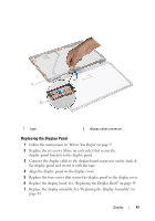
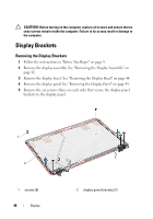
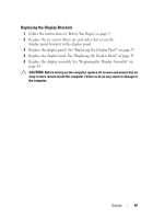
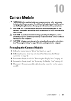
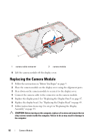
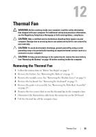
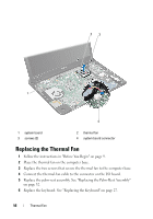
2 1 1 camera cable connector 2 camera module 6 Lift the camera module off the display cover. Replacing the Camera Module 1 Follow the instructions in "Before You Begin" on page 9. 2 Place the camera module on the display cover using the alignment posts. 3 Press down on the camera module to secure it to the display cover. 4 Connect the camera cable to the connector on the camera module. 5 Replace the display panel. See "Replacing the Display Panel" on page 47. 6 Replace the display bezel. See "Replacing the Display Bezel" on page 45. 7 Follow instructions from step 2 to step 6 in "Replacing the Display Assembly" on page 44. CAUTION: Before turning on the computer, replace all screws and ensure that no stray screws remain inside the computer. Failure to do so may result in damage to the computer. 52 Camera Module
-
 1
1 -
2
-
3
-
4
-
5
-
6
-
7
-
8
-
9
-
10
-
11
-
12
-
13
-
14
-
15
-
16
-
17
-
18
-
19
-
20
-
21
-
22
-
23
-
24
-
25
-
26
-
27
-
28
-
29
-
30
-
31
-
32
-
33
-
34
-
35
-
36
-
37
-
38
-
39
-
40
-
41
-
42
-
43
-
44
-
45
-
46
-
 47
47 -
 48
48 -
 49
49 -
 50
50 -
 51
51 -
 52
52 -
 53
53 -
 54
54 -
 55
55 -
 56
56 -
 57
57 -
58
-
59
-
60
-
61
-
62
-
63
-
64
-
65
-
66
-
67
-
68
-
69
-
70
-
71
-
72
-
73
-
74
-
75
-
76
-
77
-
78
-
79
-
80
-
81
-
82
-
83
-
84
-
85
-
86
-
87
-
88
-
89
-
90
-
91
-
92
 |
 |
