Dell Inspiron 13z Owner's Manual - Page 64
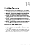
Replacing the Heat-Sink Assembly
 |
View all Dell Inspiron 13z manuals
Add to My Manuals
Save this manual to your list of manuals |
Page 64 highlights
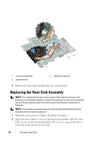
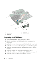
3 2 1 1 heat-sink assembly 3 system board 2 captive screws (3) 5 Remove the heat-sink assembly from the system board. Replacing the Heat-Sink Assembly NOTE: The original thermal pad can be reused if the original processor and heat sink are reinstalled together. If either the processor or heat sink is replaced, use the thermal pad provided in the kit to ensure that thermal conductivity is achieved. NOTE: This procedure assumes that you have already removed the heat-sink assembly and are ready to replace it. 1 Follow the instructions in "Before You Begin" on page 9. 2 Align the three captive screws on the heat-sink assembly with the screw holes on the system board and tighten the screws in sequential order as indicated on the processor heat sink. 64 Processor Heat Sink
-
 1
1 -
2
-
3
-
4
-
5
-
6
-
7
-
8
-
9
-
10
-
11
-
12
-
13
-
14
-
15
-
16
-
17
-
18
-
19
-
20
-
21
-
22
-
23
-
24
-
25
-
26
-
27
-
28
-
29
-
30
-
31
-
32
-
33
-
34
-
35
-
36
-
37
-
38
-
39
-
40
-
41
-
42
-
43
-
44
-
45
-
46
-
47
-
48
-
49
-
50
-
51
-
52
-
53
-
54
-
55
-
56
-
57
-
58
-
 59
59 -
 60
60 -
 61
61 -
 62
62 -
 63
63 -
 64
64 -
 65
65 -
 66
66 -
 67
67 -
 68
68 -
 69
69 -
70
-
71
-
72
-
73
-
74
-
75
-
76
-
77
-
78
-
79
-
80
-
81
-
82
-
83
-
84
-
85
-
86
-
87
-
88
-
89
-
90
-
91
-
92
 |
 |
