Dell Inspiron 3030 Desktop Owners Manual - Page 68
Installing the processor fan and heat-sink assembly
 |
View all Dell Inspiron 3030 Desktop manuals
Add to My Manuals
Save this manual to your list of manuals |
Page 68 highlights
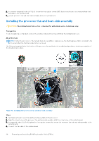
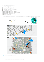
2. In a reverse sequential order (4>3>2>1) loosen the four captive screws (M3) that secure the processor fan and heat-sink assembly to the system board. 3. Lift the processor fan and heat-sink assembly from the system board. Installing the processor fan and heat-sink assembly CAUTION: The information in this section is intended for authorized service technicians only. Prerequisites If you are replacing a component, remove the existing component before performing the installation process. About this task NOTE: If either the processor or the fan and heat-sink assembly is replaced, use the thermal grease that is provided in the kit to ensure that the thermal conductivity is achieved. The following image indicates the location of the processor fan and heat-sink assembly and provides a visual representation of the installation procedure. Figure 41. Installing the processor fan and heat-sink assembly Steps 1. Gently place the processor fan and heat-sink assembly on the processor. 2. Align the screw holes on the processor fan and heat-sink assembly with the screw holes on the system board. 3. In sequential order (1>2>3>4) tighten the four captive screws that secure the processor fan and heat-sink assembly to the system board. 4. Connect the fan cable to the system board. 68 Removing and installing Field Replaceable Units (FRUs)
-
 1
1 -
2
-
3
-
4
-
5
-
6
-
7
-
8
-
9
-
10
-
11
-
12
-
13
-
14
-
15
-
16
-
17
-
18
-
19
-
20
-
21
-
22
-
23
-
24
-
25
-
26
-
27
-
28
-
29
-
30
-
31
-
32
-
33
-
34
-
35
-
36
-
37
-
38
-
39
-
40
-
41
-
42
-
43
-
44
-
45
-
46
-
47
-
48
-
49
-
50
-
51
-
52
-
53
-
54
-
55
-
56
-
57
-
58
-
59
-
60
-
61
-
62
-
 63
63 -
 64
64 -
 65
65 -
 66
66 -
 67
67 -
 68
68 -
 69
69 -
 70
70 -
 71
71 -
 72
72 -
 73
73 -
74
-
75
-
76
-
77
-
78
-
79
-
80
-
81
-
82
-
83
-
84
-
85
-
86
-
87
-
88
-
89
-
90
-
91
-
92
-
93
-
94
-
95
-
96
-
97
-
98
-
99
-
100
-
101
 |
 |
