Dell Inspiron 3030 Desktop Owners Manual - Page 73
Installing the system board, Removing the system board
 |
View all Dell Inspiron 3030 Desktop manuals
Add to My Manuals
Save this manual to your list of manuals |
Page 73 highlights
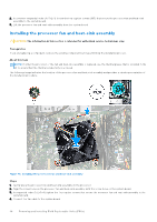
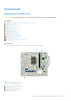
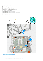
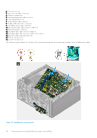
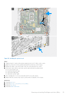
Figure 46. Removing the system board Steps 1. Remove the two screws (6-32) that secure the front I/O-bracket to the chassis. 2. Remove and lift the front I/O-bracket from the chassis. 3. Disconnect all the cables that are connected to the system board. ● processor-power cable ● system-board power cable ● optical-drive data cable ● optical-drive power cable 4. Remove the eight screws (6-32) that secure the system board to the chassis. 5. Lift the system board at an angle and remove it from the chassis. Installing the system board CAUTION: The information in this section is intended for authorized service technicians only. Prerequisites If you are replacing a component, remove the existing component before performing the installation process. About this task The following image indicates the slots and connectors on your system board. 1. processor-power cable connector Removing and installing Field Replaceable Units (FRUs) 73
-
 1
1 -
2
-
3
-
4
-
5
-
6
-
7
-
8
-
9
-
10
-
11
-
12
-
13
-
14
-
15
-
16
-
17
-
18
-
19
-
20
-
21
-
22
-
23
-
24
-
25
-
26
-
27
-
28
-
29
-
30
-
31
-
32
-
33
-
34
-
35
-
36
-
37
-
38
-
39
-
40
-
41
-
42
-
43
-
44
-
45
-
46
-
47
-
48
-
49
-
50
-
51
-
52
-
53
-
54
-
55
-
56
-
57
-
58
-
59
-
60
-
61
-
62
-
63
-
64
-
65
-
66
-
67
-
 68
68 -
 69
69 -
 70
70 -
 71
71 -
 72
72 -
 73
73 -
 74
74 -
 75
75 -
 76
76 -
 77
77 -
 78
78 -
79
-
80
-
81
-
82
-
83
-
84
-
85
-
86
-
87
-
88
-
89
-
90
-
91
-
92
-
93
-
94
-
95
-
96
-
97
-
98
-
99
-
100
-
101
 |
 |
