Dell Inspiron 3030 Desktop Owners Manual - Page 70
Installing the processor, About this task
 |
View all Dell Inspiron 3030 Desktop manuals
Add to My Manuals
Save this manual to your list of manuals |
Page 70 highlights
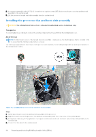
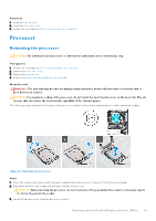
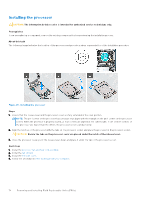
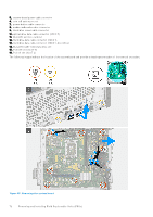
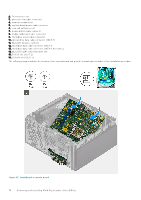
Installing the processor CAUTION: The information in this section is intended for authorized service technicians only. Prerequisites If you are replacing a component, remove the existing component before performing the installation process. About this task The following image indicates the location of the processor and provides a visual representation of the installation procedure. Figure 43. Installing the processor Steps 1. Ensure that the release lever and the processor cover are fully extended in the open position. NOTE: The pin 1 corner of the processor has a triangle that aligns with the triangle on the pin 1 corner on the processor socket. When the processor is properly seated, all four corners are aligned at the same height. If one or more corners of the processor are higher than the others, the processor is not seated properly. 2. Align the notches on the processor with the tabs on the processor socket and place the processor in the processor socket. CAUTION: Ensure the tabs on the processor cover are placed under the notch of the release lever. 3. Close the processor cover, pivot the release lever down, and place it under the tab on the processor socket. Next steps 1. Install the processor fan and heat-sink assembly. 2. Install the fan shroud. 3. Install the left-side cover. 4. Follow the procedure in After working inside your computer. 70 Removing and installing Field Replaceable Units (FRUs)
-
 1
1 -
2
-
3
-
4
-
5
-
6
-
7
-
8
-
9
-
10
-
11
-
12
-
13
-
14
-
15
-
16
-
17
-
18
-
19
-
20
-
21
-
22
-
23
-
24
-
25
-
26
-
27
-
28
-
29
-
30
-
31
-
32
-
33
-
34
-
35
-
36
-
37
-
38
-
39
-
40
-
41
-
42
-
43
-
44
-
45
-
46
-
47
-
48
-
49
-
50
-
51
-
52
-
53
-
54
-
55
-
56
-
57
-
58
-
59
-
60
-
61
-
62
-
63
-
64
-
 65
65 -
 66
66 -
 67
67 -
 68
68 -
 69
69 -
 70
70 -
 71
71 -
 72
72 -
 73
73 -
 74
74 -
 75
75 -
76
-
77
-
78
-
79
-
80
-
81
-
82
-
83
-
84
-
85
-
86
-
87
-
88
-
89
-
90
-
91
-
92
-
93
-
94
-
95
-
96
-
97
-
98
-
99
-
100
-
101
 |
 |
