Dell Inspiron 3030 Small Desktop Owners Manual - Page 68
Installing the processor fan and heat-sink assembly
 |
View all Dell Inspiron 3030 Small Desktop manuals
Add to My Manuals
Save this manual to your list of manuals |
Page 68 highlights
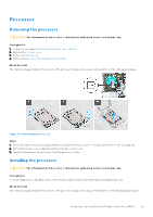
Installing the processor fan and heat-sink assembly CAUTION: The information in this section is intended for authorized service technicians only. Prerequisites If you are replacing a component, remove the existing component before performing the installation process. About this task The following images indicate the location of the fan and heat-sink assembly and provide a visual representation of the installation procedure. Figure 49. Installing the fan and heat-sink assembly Steps 1. Gently align and place the processor fan and heat-sink assembly on the processor. NOTE: The side of the fan with the word 'REAR' written must face the rear of the chassis. NOTE: The stubs on the fan shroud must align to the corresponding stub holes on the processor fan. 2. Align the screw holes on the processor fan and heat-sink assembly with the screw holes on the system board. 3. In a sequential order (1>2>3>4), tighten the four captive screws to secure the processor fan and heat-sink assembly on the system board. 4. Connect the fan and heat-sink assembly cable to the connector on the system board. Next steps 1. Install the hard-drive and optical-drive cage. 2. Install the fan shroud. 3. Install the left-side cover. 4. Follow the procedure in After working inside your computer. 68 Removing and installing Field Replaceable Units (FRUs)
-
 1
1 -
2
-
3
-
4
-
5
-
6
-
7
-
8
-
9
-
10
-
11
-
12
-
13
-
14
-
15
-
16
-
17
-
18
-
19
-
20
-
21
-
22
-
23
-
24
-
25
-
26
-
27
-
28
-
29
-
30
-
31
-
32
-
33
-
34
-
35
-
36
-
37
-
38
-
39
-
40
-
41
-
42
-
43
-
44
-
45
-
46
-
47
-
48
-
49
-
50
-
51
-
52
-
53
-
54
-
55
-
56
-
57
-
58
-
59
-
60
-
61
-
62
-
 63
63 -
 64
64 -
 65
65 -
 66
66 -
 67
67 -
 68
68 -
 69
69 -
 70
70 -
 71
71 -
 72
72 -
 73
73 -
74
-
75
-
76
-
77
-
78
-
79
-
80
-
81
-
82
-
83
-
84
-
85
-
86
-
87
-
88
-
89
-
90
-
91
-
92
-
93
-
94
-
95
-
96
-
97
-
98
-
99
-
100
 |
 |
