Dell Inspiron 3030 Small Desktop Owners Manual - Page 71
System-board connectors, Processor-power cable connector ATX CPU1
 |
View all Dell Inspiron 3030 Small Desktop manuals
Add to My Manuals
Save this manual to your list of manuals |
Page 71 highlights
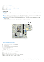
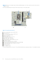
8. Remove the wireless card. 9. Remove the coin-cell battery. 10. Remove the media-card reader, if applicable. 11. Remove the fan shroud. 12. Remove the processor fan and heat-sink assembly. 13. Remove the processor. About this task NOTE: The Service Tag information of your computer is stored in the system board. You must enter the Service Tag in the BIOS setup program after you replace the system board. NOTE: Replacing the system board removes any changes that you have made to the BIOS using the BIOS setup program. You must make the appropriate changes again after you replace the system board. NOTE: Before disconnecting the cables from the system board, take a note of the connector locations to reconnect the cables correctly. The following image indicates the location of the connectors and slots of the system board. Figure 52. System-board connectors 1. Processor-power cable connector (ATX CPU1) 2. Processor socket 3. Processor-power cable connector (ATX CPU2) 4. Processor-fan cable connector 5. Memory module slots 6. M.2 2230/2280 solid-state drive slot 7. Power-button cable connector 8. Media-card reader cable connector 9. System-board power cable connector (ATX SYS) 10. M.2 wireless-card slot 11. Optical-drive data cable connector (SATA-3) 12. Hard-drive and optical-drive power cable connector (SATA PWR) 13. Hard-drive data cable connector (SATA-0, boot drive) Removing and installing Field Replaceable Units (FRUs) 71
-
 1
1 -
2
-
3
-
4
-
5
-
6
-
7
-
8
-
9
-
10
-
11
-
12
-
13
-
14
-
15
-
16
-
17
-
18
-
19
-
20
-
21
-
22
-
23
-
24
-
25
-
26
-
27
-
28
-
29
-
30
-
31
-
32
-
33
-
34
-
35
-
36
-
37
-
38
-
39
-
40
-
41
-
42
-
43
-
44
-
45
-
46
-
47
-
48
-
49
-
50
-
51
-
52
-
53
-
54
-
55
-
56
-
57
-
58
-
59
-
60
-
61
-
62
-
63
-
64
-
65
-
 66
66 -
 67
67 -
 68
68 -
 69
69 -
 70
70 -
 71
71 -
 72
72 -
 73
73 -
 74
74 -
 75
75 -
 76
76 -
77
-
78
-
79
-
80
-
81
-
82
-
83
-
84
-
85
-
86
-
87
-
88
-
89
-
90
-
91
-
92
-
93
-
94
-
95
-
96
-
97
-
98
-
99
-
100
 |
 |
