Dell Inspiron 3030 Small Desktop Owners Manual - Page 76
Installing the I/O bracket, processor-power cable
 |
View all Dell Inspiron 3030 Small Desktop manuals
Add to My Manuals
Save this manual to your list of manuals |
Page 76 highlights
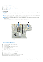
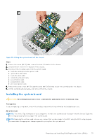
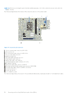
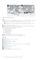
Figure 59. Installing the I/O bracket Steps 1. Slide the system board at an angle and align the rear external ports to their respective openings on the chassis. NOTE: The side of the fan with the word 'REAR' written must face the rear of the chassis. NOTE: The stubs on the fan shroud must align to the corresponding stub holes on the processor fan. 2. Place the system board onto the chassis. 3. Replace the seven screws (#6-32) and the screw (#6-32x3.8) to secure the system board on the chassis. 4. Route and connect the following cables to the system board. ● hard-drive and optical-drive power cable ● optical-drive data cable ● hard-drive data cable ● system-board power cable ● power-button cable ● power-button cable ● processor-power cable 5. Align and place the front I/O bracket with I/O slot on the chassis. 6. Replace the screw (#6-32) to secure the front I/O bracket on the chassis. Next steps 1. Install the processor. 2. Install the processor fan and heat-sink assembly. 3. Install the fan shroud. 4. Install the media-card reader, if applicable. 5. Install the coin-cell battery. 6. Install the wireless card. 7. Install the M.2 2230 solid-state drive or the M.2 2280 solid-state drive, whichever applicable. 8. Install the memory. 9. Install the hard-drive and optical-drive cage. 10. Install the 3.5-inch hard drive. 11. Install the front cover. 12. Install the left-side cover. 13. Follow the procedure in After working inside your computer. 76 Removing and installing Field Replaceable Units (FRUs)
-
 1
1 -
2
-
3
-
4
-
5
-
6
-
7
-
8
-
9
-
10
-
11
-
12
-
13
-
14
-
15
-
16
-
17
-
18
-
19
-
20
-
21
-
22
-
23
-
24
-
25
-
26
-
27
-
28
-
29
-
30
-
31
-
32
-
33
-
34
-
35
-
36
-
37
-
38
-
39
-
40
-
41
-
42
-
43
-
44
-
45
-
46
-
47
-
48
-
49
-
50
-
51
-
52
-
53
-
54
-
55
-
56
-
57
-
58
-
59
-
60
-
61
-
62
-
63
-
64
-
65
-
66
-
67
-
68
-
69
-
70
-
 71
71 -
 72
72 -
 73
73 -
 74
74 -
 75
75 -
 76
76 -
 77
77 -
 78
78 -
 79
79 -
 80
80 -
 81
81 -
82
-
83
-
84
-
85
-
86
-
87
-
88
-
89
-
90
-
91
-
92
-
93
-
94
-
95
-
96
-
97
-
98
-
99
-
100
 |
 |
