Dell Inspiron 530 Service Manual
Dell Inspiron 530 - Desktop -Intel Celeron Processor 450 Manual
 |
UPC - 883685981020
View all Dell Inspiron 530 manuals
Add to My Manuals
Save this manual to your list of manuals |
Dell Inspiron 530 manual content summary:
- Dell Inspiron 530 | Service Manual - Page 1
Dell™ Latitude™ D530 Service Manual Before You Begin Internal Card With Bluetooth ® Wireless Technology Hard Drive Memory Module Modem Coin-Cell Battery Hinge Cover Keyboard Mini-Card Display Assembly Palm Rest System Fan Processor Thermal-Cooling Assembly Processor Module Speaker Assembly Base - Dell Inspiron 530 | Service Manual - Page 2
Back to Contents Page Before You Begin Dell™ Latitude™ D530 Service Manual Recommended Tools Turning Off Your Computer Before Working Inside Your Computer This chapter provides procedures for removing and installing the components in your computer. Unless otherwise noted, each procedure assumes that - Dell Inspiron 530 | Service Manual - Page 3
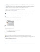
the network device. 4. Disconnect all telephone or network cables from the computer. NOTICE: To avoid damaging the system board, you must remove the main battery before you service the computer. 5. Disconnect your computer and all attached devices from their electrical outlets. 6. Close the display - Dell Inspiron 530 | Service Manual - Page 4
to Contents Page Flashing the BIOS Dell™ Latitude™ D530 Service Manual 1. Download the BIOS utility from the Dell Support website at support.dell.com and save it to your desktop. 2. After the download completes, double-click the BIOS utility file. 3. In the Dell BIOS Flash window, click Continue - Dell Inspiron 530 | Service Manual - Page 5
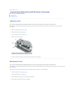
to Contents Page Internal Card With Bluetooth® Wireless Technology Dell™ Latitude™ D530 Service Manual Adding the Card Removing the Card Adding the Card CAUTION: Before performing the following procedures, read the safety instructions in your Product Information Guide. NOTICE: To avoid electrostatic - Dell Inspiron 530 | Service Manual - Page 6
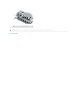
1 system board connector 2 card 3 cable connector NOTICE: Be careful when removing the card to avoid damaging the card, card cable, or surrounding components. Back to Contents Page - Dell Inspiron 530 | Service Manual - Page 7
Back to Contents Page Coin-Cell Battery Dell™ Latitude™ D530 Service Manual CAUTION: Before performing the following procedures, follow the safety instructions in your Product Information Guide. NOTICE: To avoid electrostatic discharge, ground yourself by using a wrist grounding strap or by - Dell Inspiron 530 | Service Manual - Page 8
Back to Contents Page Processor Module Dell™ Latitude™ D530 Service Manual Removing the Processor Module Replacing the Processor Module Removing the Processor Module CAUTION: Before you begin the following procedure, follow the safety instructions in the Product Information Guide. NOTICE: To avoid - Dell Inspiron 530 | Service Manual - Page 9
the others, the module is not seated correctly. 2. Tighten the ZIF socket by turning the cam screw clockwise to secure the processor module to the system board. 3. Perform the steps in Removing the Processor Module in reverse order, beginning with step 4. Back to Contents Page - Dell Inspiron 530 | Service Manual - Page 10
Dell™ Latitude™ D530 Service Manual Removing the Processor Thermal-Cooling Assembly Replacing the Processor Thermal-Cooling Assembly Removing the Processor Thermal-Cooling Assembly CAUTION: Before you begin the following procedure, follow the safety instructions in the Product Information Guide - Dell Inspiron 530 | Service Manual - Page 11
2. Tighten the six captive screws, labeled "1" through "6," in consecutive order. Back to Contents Page - Dell Inspiron 530 | Service Manual - Page 12
Dell™ Latitude™ D530 Service Manual Removing the Display Assembly Removing the Display Bezel Replacing the Display Bezel Display Panel Display Latch Removing the Display Assembly CAUTION: Before you begin the following procedure, follow the safety instructions in the Product Information Guide - Dell Inspiron 530 | Service Manual - Page 13
the safety instructions in the Product Information Guide. NOTICE: To avoid electrostatic discharge, ground yourself by using a wrist grounding strap or by periodically touching an unpainted metal surface (such as the back panel) on the computer. NOTICE: To help prevent damage to the system board - Dell Inspiron 530 | Service Manual - Page 14
procedure, follow the safety instructions in the Product Information Guide. NOTICE: To avoid electrostatic discharge, ground yourself by using a wrist grounding strap or by touching an unpainted metal surface on the computer. NOTICE: To help prevent damage to the system board, you must remove - Dell Inspiron 530 | Service Manual - Page 15
procedure, follow the safety instructions in the Product Information Guide. NOTICE: To avoid electrostatic discharge, ground yourself by using a wrist grounding strap or by touching an unpainted metal surface on the computer. NOTICE: To help prevent damage to the system board, you must remove - Dell Inspiron 530 | Service Manual - Page 16
2. Replace the support bracket and replace the M2 x 4-mm screw. Back to Contents Page - Dell Inspiron 530 | Service Manual - Page 17
Back to Contents Page System Fan Dell™ Latitude™ D530 Service Manual CAUTION: Before you begin the following procedure, follow the safety instructions in the Product Information Guide. NOTICE: To avoid electrostatic discharge, ground yourself by using a wrist grounding strap or by periodically - Dell Inspiron 530 | Service Manual - Page 18
mode to conserve the amount of electrical power allocated to each device attached to the computer. AGP - accelerated graphics port - A dedicated graphics port that allows system memory to be used for video-related tasks. AGP delivers a smooth, true-color video image because of the faster interface - Dell Inspiron 530 | Service Manual - Page 19
disk drive, printer, or keyboard that is installed in or connected to your computer. device driver - See driver. DIMM - dual in-line memory module - A circuit board with memory chips that connects to a memory module on the system board. DIN connector - A round, six-pin connector that conforms to DIN - Dell Inspiron 530 | Service Manual - Page 20
to the system bus. ExpressCard - A removable I/O card adhering to the PCMCIA standard. Modems and network adapters are common types of ExpressCards. ExpressCards support both the PCI Express and USB 2.0 standard. Express Service Code - A numeric code located on a sticker on your Dell™ computer. Use - Dell Inspiron 530 | Service Manual - Page 21
before you shut down the computer. Your computer can contain several different forms of memory, such as RAM, ROM, and video memory. Frequently, the word memory is used as a synonym for RAM. memory address - A specific location where data is temporarily stored in RAM. memory mapping - The process by - Dell Inspiron 530 | Service Manual - Page 22
, such as memory, hard drives, and video. If no problems are detected during POST, the computer continues the start-up. processor - A computer chip that interprets and executes program instructions. Sometimes the processor is referred to as the CPU (central processing unit). PS/2 - personal system - Dell Inspiron 530 | Service Manual - Page 23
video cards and controllers that supports resolutions up to 1280 x 1024. SXGA+ - super-extended graphics array plus - A video standard for video cards and controllers that supports resolutions up to 1400 x 1050. system board - The main circuit board in your computer. Also known as the motherboard - Dell Inspiron 530 | Service Manual - Page 24
the computer. U UMA - unified memory allocation - System memory dynamically allocated to video. UPS - uninterruptible power supply - A backup power source used when the electrical power fails or drops to an unacceptable voltage level. A UPS keeps a computer running for a limited amount of time when - Dell Inspiron 530 | Service Manual - Page 25
resolutions up to 1280 x 800. X XGA - extended graphics array - A video standard for video cards and controllers that supports resolutions up to 1024 x 768. Z ZIF - zero insertion force - A type of socket or connector that allows a computer chip to be installed or removed with no stress applied to - Dell Inspiron 530 | Service Manual - Page 26
fragile; even a slight bump can damage the drive. NOTE: Dell does not guarantee compatibility or provide support for hard drives from sources other than Dell. 1. Follow the instructions in Before Working Inside Your Computer. 2. Turn the computer upside-down and remove the two M3 x 5-mm screws - Dell Inspiron 530 | Service Manual - Page 27
Returning a Hard Drive to Dell Return your old hard drive to Dell in its original or comparable foam packaging. Otherwise, the hard drive may be damaged in transit. 1 hard drive 2 foam packaging Back to Contents Page - Dell Inspiron 530 | Service Manual - Page 28
Dell™ Latitude™ D530 Service Manual CAUTION: Before you begin the following procedure, follow the safety instructions in the Product Information Guide careful when removing the hinge cover. 1. Follow the instructions in Before Working Inside Your Computer. 2. Open the display all the way (180 degrees - Dell Inspiron 530 | Service Manual - Page 29
Back to Contents Page Keyboard Dell™ Latitude™ D530 Service Manual Removing the Keyboard Replacing the Keyboard CAUTION: Before you begin any of the procedures in this section, follow the safety instructions in the Product Information Guide. NOTICE: To avoid electrostatic discharge, ground yourself - Dell Inspiron 530 | Service Manual - Page 30
Back to Contents Page - Dell Inspiron 530 | Service Manual - Page 31
Back to Contents Page Base Latch Dell™ Latitude™ D530 Service Manual CAUTION: Before you begin the following procedure, follow the safety instructions in the Product Information Guide. NOTICE: To avoid electrostatic discharge, ground yourself by using a wrist grounding strap or by periodically - Dell Inspiron 530 | Service Manual - Page 32
to Contents Page Memory Module Dell™ Latitude™ D530 Service Manual DIMM B Memory Module DIMM A Memory Module Verify Memory Size You can increase your computer memory by installing memory modules on the system board. See the Product Information Guide for information on the memory supported by your - Dell Inspiron 530 | Service Manual - Page 33
the keyboard from the computer is not required to access the DIMM A memory module bay. 1. Remove the hinge cover (see Hinge Cover). 2. Remove the two M2.5 x 5-mm screws at the top of the keyboard. NOTICE: The keycaps on the keyboard are fragile, easily dislodged, and time-consuming to replace. Be - Dell Inspiron 530 | Service Manual - Page 34
the computer. As the computer boots, it detects the additional memory and automatically updates the system configuration information. To confirm the amount of memory installed in the computer: l In the Microsoft® Windows® XP operating system, right-click the My Computer icon on your desktop. Click - Dell Inspiron 530 | Service Manual - Page 35
Card Dell™ Latitude™ D530 Service Manual Wireless Local Area Network (WLAN) Cards CAUTION: Before you begin the following procedure, follow the safety instructions in the Product Information Guide. NOTICE: To prevent damage to the system board, remove the main battery before you service the computer - Dell Inspiron 530 | Service Manual - Page 36
a. Move any antenna cables out of the way to make space for the WLAN card. b. Align the card with the connector at a 45-degree angle, and press the card into the connector until it clicks. NOTE: For more specific information about which cable to connect to which connector, see the documentation that - Dell Inspiron 530 | Service Manual - Page 37
Back to Contents Page Modem Dell™ Latitude™ D530 Service Manual Removing the Modem Replacing the Modem Removing the Modem CAUTION: Before you begin the following procedure, follow the safety instructions in the Product Information Guide. NOTICE: To avoid electrostatic discharge, ground yourself by - Dell Inspiron 530 | Service Manual - Page 38
that the modem cable is routed correctly when you replace the modem. 2. Connect the modem to the system board. Align the connector on the bottom of the modem with the modem connector on the system board, and press down on the right side of the modem. 3. Replace the M2 x 3-mm screw. Captive - Dell Inspiron 530 | Service Manual - Page 39
Back to Contents Page Palm Rest Dell™ Latitude™ D530 Service Manual Removing the Palm Rest Replacing the Palm Rest Removing the Palm Rest CAUTION: Before you begin the following procedure, follow the safety instructions in the Product Information Guide. NOTICE: To avoid electrostatic discharge, - Dell Inspiron 530 | Service Manual - Page 40
the safety instructions in the Product Information Guide. NOTICE: To avoid electrostatic discharge, ground yourself by using a wrist grounding strap or by periodically touching an unpainted metal surface (such as the back panel) on the computer. NOTICE: To help prevent damage to the system board - Dell Inspiron 530 | Service Manual - Page 41
Pin Assignments for I/O Connectors Dell™ Latitude™ D530 Service Manual IEEE 1394 Connector USB Connector Video Connector S-Video TV-Out Connector IEEE 1394 Connector Pin Signal 1 TPB- 2 TPB+ 3 TPA- 4 TPA+ USB Connector Pin Signal 1 USB5V+ 2 USBP- 3 USBP+ 4 GND Video Connector Pin Signal Pin Signal - Dell Inspiron 530 | Service Manual - Page 42
5 GND 13 CRT_HS 6 GND 14 CRT_VS 7 GND 15 DDC_CLK 8 GND S-Video TV-Out Connector S-Video Pin Signal 1 GND 2 GND 3 DLUMA-L 4 DCRMA-L Composite Video Pin Signal 5 NC 6 DCMPS-L 7 GND Back to Contents Page - Dell Inspiron 530 | Service Manual - Page 43
Back to Contents Page Speaker Assembly Dell™ Latitude™ D530 Service Manual Removing the Speaker Assembly Replacing the Speaker Assembly Removing the Speaker Assembly CAUTION: Before you begin the following procedure, follow the safety instructions in the Product Information Guide. NOTICE: To avoid - Dell Inspiron 530 | Service Manual - Page 44
2. Replace the M2.5 x 5-mm screw that secures the speaker assembly in place. Back to Contents Page - Dell Inspiron 530 | Service Manual - Page 45
Contents Page System Board Assembly Dell™ Latitude™ D530 Service Manual Removing the System Board Assembly Replacing the System Board Assembly Removing the System Board Assembly CAUTION: Before you begin the following procedure, follow the safety instructions in the Product Information Guide. NOTICE - Dell Inspiron 530 | Service Manual - Page 46
may result in damage to the computer. 2. Turn on the computer. NOTE: If you use a BIOS update program CD to flash the BIOS, press before inserting the CD so that you can set up the computer to boot from a CD this one time only. Otherwise, you must enter the system setup program to change the - Dell Inspiron 530 | Service Manual - Page 47
4. Enter the system setup program to update the BIOS on the new system board with the computer Service Tag. Back to Contents Page - Dell Inspiron 530 | Service Manual - Page 48
Back to Contents Page Dell™ Latitude™ D530 Service Manual NOTE: A NOTE indicates important information that helps you make better use of your computer. NOTICE: A NOTICE indicates either potential damage to hardware or loss of data and tells you how to avoid the problem. CAUTION: A CAUTION indicates
-
 1
1 -
 2
2 -
 3
3 -
 4
4 -
 5
5 -
 6
6 -
 7
7 -
8
-
9
-
10
-
11
-
12
-
13
-
14
-
15
-
16
-
17
-
18
-
19
-
20
-
21
-
22
-
23
-
24
-
25
-
26
-
27
-
28
-
29
-
30
-
31
-
32
-
33
-
34
-
35
-
36
-
37
-
38
-
39
-
40
-
41
-
42
-
43
-
44
-
45
-
46
-
47
-
48
 |
 |
Dell™ Latitude™ D530 Service Manual
Model PP17L
November 2007
Rev. A00
Model PP17L
Notes, Notices, and Cautions
Information in this document is subject to change without notice.
© 2007 Dell Inc. All rights reserved.
Reproduction in any manner whatsoever without the written permission of Dell Inc. is strictly forbidden.
Trademarks used in this text:
Dell
, the
DELL
logo,
Latitude, and Dell OpenManage
are trademarks of Dell Inc.;
Intel
,
Pentium, and Celeron
are registered trademarks of Intel
Corporation;
Microsoft
,
Windows, Windows Server, Windows XP, MS-DOS and Windows Vista
are either trademarks or registered trademarks of Microsoft Corporation in the United
States and/or other countries.
Other trademarks and trade names may be used in this document to refer to either the entities claiming the marks and names or their products. Dell Inc. disclaims any
proprietary interest in trademarks and trade names other than its own.
Before You Begin
Palm Rest
Internal Card With Bluetooth
®
Wireless Technology
System Fan
Hard Drive
Processor Thermal
-
Cooling Assembly
Memory Module
Processor Module
Modem
Speaker Assembly
Coin
-
Cell Battery
Base Latch
Hinge Cover
System Board Assembly
Keyboard
Flashing the BIOS
Mini
-
Card
Pin Assignments for I/O Connectors
Display Assembly
Glossary
NOTE:
A NOTE indicates important information that helps you make better use of your computer.
NOTICE:
A NOTICE indicates either potential damage to hardware or loss of data and tells you how to avoid the problem.
CAUTION:
A CAUTION indicates a potential for property damage, personal injury, or death.