Dell Inspiron 530 Service Manual - Page 45
System Board Assembly
 |
UPC - 883685981020
View all Dell Inspiron 530 manuals
Add to My Manuals
Save this manual to your list of manuals |
Page 45 highlights
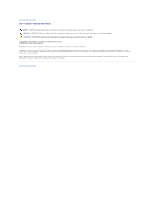
Back to Contents Page System Board Assembly Dell™ Latitude™ D530 Service Manual Removing the System Board Assembly Replacing the System Board Assembly Removing the System Board Assembly CAUTION: Before you begin the following procedure, follow the safety instructions in the Product Information Guide. NOTICE: To avoid electrostatic discharge, ground yourself by using a wrist grounding strap or by periodically touching an unpainted metal surface (such as the back panel) on the computer. NOTICE: To help prevent damage to the system board, remove the main battery (see Before Working Inside Your Computer) before working inside the computer. The system board's BIOS chip contains the Service Tag, which is also visible on a barcode label on the bottom of the computer. The replacement kit for the system board includes a CD that provides a utility for transferring the Service Tag to the replacement system board. 1. Follow the instructions in Before You Begin. 2. Remove the hard drive (see Removing the Hard Drive). 3. Remove the memory module(s) (see Memory Module). 4. Remove the modem (see Removing the Modem). 5. Remove the Mini-Card (see Mini-Card). 6. Remove the hinge cover (see Hinge Cover). 7. Remove the keyboard (see Removing the Keyboard). 8. Remove the display assembly (see Removing the Display Assembly). 9. Remove the processor thermal-cooling assembly (see Removing the Processor Thermal-Cooling Assembly). 10. Remove the processor (see Removing the Processor Module). 11. Remove the palm rest (see Removing the Palm Rest). NOTE: It is not required but is highly recommended that you remove the system fan (see System Fan) to allow easier access to the system board. 12. Remove the speaker assembly (see Removing the Speaker Assembly). 13. Remove the two M2.5 x 5-mm screws labeled "B."
-
 1
1 -
2
-
3
-
4
-
5
-
6
-
7
-
8
-
9
-
10
-
11
-
12
-
13
-
14
-
15
-
16
-
17
-
18
-
19
-
20
-
21
-
22
-
23
-
24
-
25
-
26
-
27
-
28
-
29
-
30
-
31
-
32
-
33
-
34
-
35
-
36
-
37
-
38
-
39
-
 40
40 -
 41
41 -
 42
42 -
 43
43 -
 44
44 -
 45
45 -
 46
46 -
 47
47 -
 48
48
 |
 |