Dell Inspiron 530 Service Manual - Page 9
Removing the Processor Module, Back to Contents
 |
UPC - 883685981020
View all Dell Inspiron 530 manuals
Add to My Manuals
Save this manual to your list of manuals |
Page 9 highlights
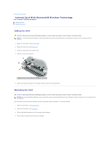
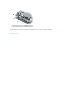
NOTICE: Ensure that the cam lock is in the fully open position before seating the processor module. Seating the processor module properly in the ZIF socket does not require force. NOTICE: A processor module that is not properly seated can result in an intermittent connection or permanent damage to the processor and ZIF socket. NOTE: If a new microprocessor is installed, you will receive one of the following: ¡ a new thermal-cooling assembly which will include an affixed thermal pad or ¡ you will receive a new thermal pad along with a tech sheet to illustrate proper installation. l Align the pin-1 corner of the processor module with the pin-1 corner of the ZIF socket, and insert the processor module. NOTE: The pin-1 corner of the processor module has a triangle that aligns with the triangle on the pin-1 corner of the ZIF socket. NOTICE: You must position the processor module correctly in the ZIF socket to avoid permanent damage to the module and the socket. When the processor module is correctly seated, all four corners are aligned at the same height. If one or more corners of the module are higher than the others, the module is not seated correctly. 2. Tighten the ZIF socket by turning the cam screw clockwise to secure the processor module to the system board. 3. Perform the steps in Removing the Processor Module in reverse order, beginning with step 4. Back to Contents Page
-
 1
1 -
2
-
3
-
 4
4 -
 5
5 -
 6
6 -
 7
7 -
 8
8 -
 9
9 -
 10
10 -
 11
11 -
 12
12 -
 13
13 -
 14
14 -
15
-
16
-
17
-
18
-
19
-
20
-
21
-
22
-
23
-
24
-
25
-
26
-
27
-
28
-
29
-
30
-
31
-
32
-
33
-
34
-
35
-
36
-
37
-
38
-
39
-
40
-
41
-
42
-
43
-
44
-
45
-
46
-
47
-
48
 |
 |