Dell Inspiron One 2020 Specifications (SWF/PDF) - Page 67
Replacing the Processor
 |
View all Dell Inspiron One 2020 manuals
Add to My Manuals
Save this manual to your list of manuals |
Page 67 highlights
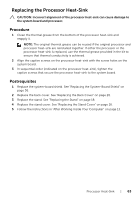
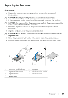
Replacing the Processor Procedure 1 Unpack the new processor, being careful not to touch the underside of the processor. CAUTION: Ground yourself by touching an unpainted metal surface. 2 If the release lever on the socket is not fully extended, move it to that position. CAUTION: You must position the processor correctly in the processor socket to avoid permanent damage to the processor. 3 Orient the alignment notches on the processor with the alignment tabs on the socket. 4 Align the pin-1 corners of the processor and socket. CAUTION: Ensure that the processor cover notch is positioned underneath the alignment post. 5 When the processor is fully seated in the socket, close the processor cover. 6 Pivot the release lever down and place it under the tab on the processor cover. 4 1 3 2 7 56 1 processor pin-1 indicator 3 alignment notches (2) 5 alignment post 7 release lever 2 processor 4 processor cover notch 6 processor cover Processor | 67
-
 1
1 -
2
-
3
-
4
-
5
-
6
-
7
-
8
-
9
-
10
-
11
-
12
-
13
-
14
-
15
-
16
-
17
-
18
-
19
-
20
-
21
-
22
-
23
-
24
-
25
-
26
-
27
-
28
-
29
-
30
-
31
-
32
-
33
-
34
-
35
-
36
-
37
-
38
-
39
-
40
-
41
-
42
-
43
-
44
-
45
-
46
-
47
-
48
-
49
-
50
-
51
-
52
-
53
-
54
-
55
-
56
-
57
-
58
-
59
-
60
-
61
-
 62
62 -
 63
63 -
 64
64 -
 65
65 -
 66
66 -
 67
67 -
 68
68 -
 69
69 -
 70
70 -
 71
71 -
 72
72 -
73
-
74
-
75
-
76
-
77
-
78
-
79
-
80
-
81
-
82
-
83
-
84
-
85
-
86
-
87
-
88
-
89
-
90
-
91
-
92
-
93
-
94
-
95
-
96
-
97
-
98
-
99
-
100
-
101
-
102
-
103
-
104
-
105
-
106
-
107
-
108
-
109
-
110
 |
 |