Dell Inspiron One 2020 Specifications (SWF/PDF) - Page 89
Replacing the Camera Module
 |
View all Dell Inspiron One 2020 manuals
Add to My Manuals
Save this manual to your list of manuals |
Page 89 highlights
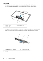
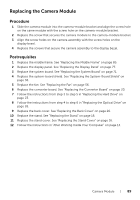
Replacing the Camera Module Procedure 1 Slide the camera module into the camera-module bracket and align the screw hole on the came module with the screw hole on the camera-module bracket. 2 Replace the screw that secures the camera module to the camera-module bracket. 3 Align the screw holes on the camera assembly with the screw holes on the display bezel. 4 Replace the screws that secure the camera assembly to the display bezel. Postrequisites 1 Replace the middle frame. See "Replacing the Middle Frame" on page 85. 2 Replace the display panel. See "Replacing the Display Panel" on page 77. 3 Replace the system board. See "Replacing the System Board" on page 71. 4 Replace the system-board shield. See "Replacing the System-Board Shield" on page 36. 5 Replace the fan. See "Replacing the Fan" on page 56. 6 Replace the converter board. See "Replacing the Converter Board" on page 30. 7 Follow the instructions from step 3 to step 5 in "Replacing the Hard Drive" on page 23. 8 Follow the instructions from step 4 to step 6 in "Replacing the Optical Drive" on page 26. 9 Replace the back cover. See "Replacing the Back Cover" on page 20. 10 Replace the stand. See "Replacing the Stand" on page 18. 11 Replace the stand cover. See "Replacing the Stand Cover" on page 16. 12 Follow the instructions in "After Working Inside Your Computer" on page 13. Camera Module | 89
-
 1
1 -
2
-
3
-
4
-
5
-
6
-
7
-
8
-
9
-
10
-
11
-
12
-
13
-
14
-
15
-
16
-
17
-
18
-
19
-
20
-
21
-
22
-
23
-
24
-
25
-
26
-
27
-
28
-
29
-
30
-
31
-
32
-
33
-
34
-
35
-
36
-
37
-
38
-
39
-
40
-
41
-
42
-
43
-
44
-
45
-
46
-
47
-
48
-
49
-
50
-
51
-
52
-
53
-
54
-
55
-
56
-
57
-
58
-
59
-
60
-
61
-
62
-
63
-
64
-
65
-
66
-
67
-
68
-
69
-
70
-
71
-
72
-
73
-
74
-
75
-
76
-
77
-
78
-
79
-
80
-
81
-
82
-
83
-
 84
84 -
 85
85 -
 86
86 -
 87
87 -
 88
88 -
 89
89 -
 90
90 -
 91
91 -
 92
92 -
 93
93 -
 94
94 -
95
-
96
-
97
-
98
-
99
-
100
-
101
-
102
-
103
-
104
-
105
-
106
-
107
-
108
-
109
-
110
 |
 |