Dell OptiPlex 745 Quick Reference Guide - Page 11
Mini Tower Computer - Back-Panel Connectors - manual
 |
UPC - 683728231774
View all Dell OptiPlex 745 manuals
Add to My Manuals
Save this manual to your list of manuals |
Page 11 highlights
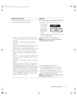
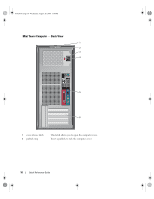
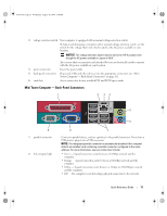
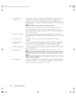
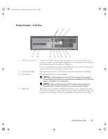
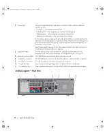
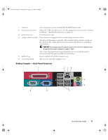
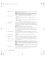
book.book Page 11 Wednesday, August 16, 2006 3:18 PM 3 voltage selection switch Your computer is equipped with a manual voltage-selection switch. To help avoid damaging a computer with a manual voltage-selection switch, set the switch for the voltage that most closely matches the AC power available in your location. NOTICE: The voltage selection switch must be set to the 115-V position even though the AC power available in Japan is 100 V. Also, ensure that your monitor and attached devices are electrically rated to operate with the AC power available in your location. 4 power connector Insert the power cable. 5 back-panel connectors Plug serial, USB, and other devices into the appropriate connectors (see "Mini Tower Computer - Back-Panel Connectors" on page 11). 6 card slots Access connectors for any installed PCI and PCI Express cards. Mini Tower Computer - Back-Panel Connectors 1 2 34 5 9 1 parallel connector 2 link integrity light 6 8 7 Connect a parallel device, such as a printer, to the parallel connector. If you have a USB printer, plug it into a USB connector. NOTE: The integrated parallel connector is automatically disabled if the computer detects an installed card containing a parallel connector configured to the same address. For more information, see your online User's Guide. • Green - A good connection exists between a 10-Mbps network and the computer. • Orange - A good connection exists between a 100-Mbps network and the computer. • Yellow - A good connection exists between a 1-Gbps (or 1000-Mbps) network and the computer. • Off - The computer is not detecting a physical connection to the network. Quick Reference Guide 11
-
 1
1 -
2
-
3
-
4
-
5
-
 6
6 -
 7
7 -
 8
8 -
 9
9 -
 10
10 -
 11
11 -
 12
12 -
 13
13 -
 14
14 -
 15
15 -
 16
16 -
17
-
18
-
19
-
20
-
21
-
22
-
23
-
24
-
25
-
26
-
27
-
28
-
29
-
30
-
31
-
32
-
33
-
34
-
35
-
36
-
37
-
38
-
39
-
40
-
41
-
42
-
43
-
44
-
45
-
46
-
47
-
48
-
49
-
50
-
51
-
52
-
53
-
54
-
55
-
56
-
57
-
58
-
59
-
60
 |
 |