Dell PowerConnect 2708 User's Guide
Dell PowerConnect 2708 Manual
 |
View all Dell PowerConnect 2708 manuals
Add to My Manuals
Save this manual to your list of manuals |
Dell PowerConnect 2708 manual content summary:
- Dell PowerConnect 2708 | User's Guide - Page 1
Dell™ PowerConnect™ 27XX Systems User's Guide www.dell.com | support.dell.com - Dell PowerConnect 2708 | User's Guide - Page 2
damage to hardware or loss of data and tells you how to avoid the problem. CAUTION: A CAUTION indicates a potential for property damage, personal injury, or Dell Inc. is strictly forbidden. Trademarks used in this text: Dell, Dell OpenManage, the DELL logo, and PowerConnect are trademarks of Dell - Dell PowerConnect 2708 | User's Guide - Page 3
9 General Features 9 MAC Address Supported Features 11 Layer 2 Features 11 VLAN Supported Features 12 Class of Service (CoS) Features 12 Ethernet Switch Management Features 13 Port Default Settings 13 2 Hardware Description Switch Port Configurations 15 PowerConnect 2708/2716/2724/2748 Front - Dell PowerConnect 2708 | User's Guide - Page 4
Surface 30 Connecting the Device to AC Power Supply 31 Connecting the Device to the Network 32 4 Starting and Configuring the Dell™ PowerConnect™ 27XX Viewing Switch Operation 33 Initial Configuration 33 5 Using the Dell™ OpenManage™ Switch Administrator Understanding the Interface 37 Using - Dell PowerConnect 2708 | User's Guide - Page 5
System Information Defining Switch Information 43 Viewing the Switch Status 43 Viewing System IP Address 44 Defining Interface Configuration 47 Viewing Jumbo Frames 49 Creating VLAN Membership 50 Defining VLAN Interface Settings 51 Configuring LAG Membership 52 Managing System Files 54 - Dell PowerConnect 2708 | User's Guide - Page 6
6 Contents - Dell PowerConnect 2708 | User's Guide - Page 7
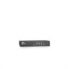
describes the hardware configurations of the PowerConnect 2708, PowerConnect 2716, PowerConnect 2724, and PowerConnect 2748. The switches are managed by Dell's OpenManage Switch Administrator. 8 1-Gigabit Ethernet Ports The following figure illustrates the PowerConnect 2708 front panel. Figure - Dell PowerConnect 2708 | User's Guide - Page 8
16 1-Gigabit Ethernet Ports The following figure illustrates the PowerConnect 2716 front panel. Figure 1-2. PowerConnect 2716 Front Panel The PowerConnect 2716 switch supports 16 GbE copper ports. 24 1-Gigabit Ethernet Ports + 2 SFP Combo ports The following figure illustrates the PowerConnect 2724 - Dell PowerConnect 2708 | User's Guide - Page 9
Secure Mode, the user presses the Managed Mode button. From Secure Mode when the Managed Mode button is pressed, the switch enters Managed Mode default configuration with the default IP address of 192.168.2.1. Back Pressure Support On half-duplex links, the receiving port prevents buffer overflows - Dell PowerConnect 2708 | User's Guide - Page 10
a point-to-point link segment, and to automatically configure both Ethernet switches to take maximum advantage of their transmission capabilities. Port advertisement allows the system administrator to configure the port speeds advertised. Jumbo Frames Support Jumbo frames are frames with an MTU - Dell PowerConnect 2708 | User's Guide - Page 11
based Switching In Managed or Secure mode, the switch system always performs VLAN-aware bridging. Classic bridging (IEEE802.1D) is not performed (where frames are forwarded based only on their destination MAC address). However, a similar functionality may be configured for untagged frames. Addresses - Dell PowerConnect 2708 | User's Guide - Page 12
Port-based VLANs classify incoming packets to VLANs based on their ingress port. Link Aggregation The PowerConnect 2708/2716/2724/2748 switches support up to six aggregated links. Each of the six aggregated links may be defined with up to four member ports to form a single Link Aggregated Group (LAG - Dell PowerConnect 2708 | User's Guide - Page 13
using the Web management interface in the system. Port Default Settings The PowerConnect 2708/2716/2724/2748 devices's port default settings are as follows: Function Flow Control (user-configurable) Backpressure (user-configurable) Auto Negotiation Speed (user-configurable) Auto Negotiation Duplex - Dell PowerConnect 2708 | User's Guide - Page 14
14 - Dell PowerConnect 2708 | User's Guide - Page 15
Port Configurations PowerConnect 2708/2716/2724/2748 Front Panel Port Description The Dell™ PowerConnect™ 2708, 2716, 2724 and 2748 switches use 10/100/1000BASE-T ports on the front panel for connecting to a network. The Gigabit Ethernet ports can operate at 10, 100 or 1000 Mbps. These ports support - Dell PowerConnect 2708 | User's Guide - Page 16
the Ethernet switch operational status. The Power LED on the front panel indicates whether the device is powered on or not. A Managed Mode push-button, located on the right side on the front panel, restores the device's default settings configuration. Figure 2-4. PowerConnect 2716 Back Panel 16 - Dell PowerConnect 2708 | User's Guide - Page 17
indicates the Ethernet switch operational status. The Power LED on the front panel indicates whether the device is powered on or not. A Managed Mode push-button, located on the far right side on the front panel, restores the device's default settings configuration. Figure 2-6. PowerConnect 2724 Back - Dell PowerConnect 2708 | User's Guide - Page 18
is powered on or not. A Managed Mode push-button, located on the far right side on the front panel, sets the device management mode. The back panel contains an AC Power Supply Interface. The following figure illustrates the back panel of the PowerConnect 2748 device. Figure 2-8. PowerConnect 2748 - Dell PowerConnect 2708 | User's Guide - Page 19
of links, power supply, fan status, and Managed Mode status. Power LED On the PowerConnect 2708/2716/2724/2748 front panel there is a Power LED. The following table describes the Power Supply status LED indications. Table 2-1. Power LED Indications LED Color Green Solid Off Description The switch - Dell PowerConnect 2708 | User's Guide - Page 20
Off Description Indicates diagnostics in progress, firmware loading, or Managed Mode transition. Indicates the switch is in Managed Mode. Diagnostics has failed. No valid image. Indicates Unmanaged mode or Secure mode (2748 only). Fan LED (2748 only) On the PowerConnect 2748 front panel there is - Dell PowerConnect 2708 | User's Guide - Page 21
(2748 only), pressing the Managed Mode button causes: • Factory default configuration (192.168.2.1) is set as the switch IP address. • Subnet mask changes to 255.255.255.0 • Graphical User Interface (GUI) login user name changes to Admin, and the password is not configured (appears blank), with Read - Dell PowerConnect 2708 | User's Guide - Page 22
ventilation. The PowerConnect 2708 and PowerConnect 2716 devices have no internal fans. Cables, Port Connections, and Pinout Information This section explains the switch physical interfaces, and provides information about cables and port connections. Copper cable diagnostics are supported. High - Dell PowerConnect 2708 | User's Guide - Page 23
the RJ-45 to the SFP (or vice versa) without a system reset. The system automatically detects the media used on a combo port, and utilizes this information in the control interfaces. PowerConnect 2724 switch supports SFP diagnostics. The optical transceiver provides access to a set of parameters - Dell PowerConnect 2708 | User's Guide - Page 24
power supply 16 Transmitter power supply 17 Transmitter ground (common with receiver ground) 18 Transmitter non-inverted data in 19 Transmitter inverted data in 20 Transmitter ground (common with receiver ground) Power Connectors The PowerConnect 2708/2716/2724/2748 switches are powered - Dell PowerConnect 2708 | User's Guide - Page 25
installing the PowerConnect switch consists of both hardware and software instructions. The process consists of physically installing these devices and configuring them. The switch is delivered from the factory in Unmanaged Mode. If the user wishes to use the switch as an unmanaged switch, they can - Dell PowerConnect 2708 | User's Guide - Page 26
to Managed Mode. The chapter "Starting and Configuring the Dell™PowerConnect™ 2708/2716/2724/2748 for Managed Mode Operation" explains how to set the switch to Managed Mode. Site Requirements The PowerConnect 2708/2716/2724/2748 devices can be mounted in a standard equipment rack, placed on a - Dell PowerConnect 2708 | User's Guide - Page 27
following items are included: • The device • AC power cable • Self-adhesive rubber pads (for on-shelf installation) • Rack-mount kit for installation • Documentation CD • Product Information Guide Unpacking the Device To unpack the PowerConnect device: NOTE: Before unpacking the device, inspect the - Dell PowerConnect 2708 | User's Guide - Page 28
instructions apply to the PowerConnect 2708/2716 instructions located in your Product Information Guide to be serviced by trained service technicians only. • Ensure that the power cable, power circuits, wiring, and over-current protection. To determine the possibility of overloading the supply - Dell PowerConnect 2708 | User's Guide - Page 29
the Device The following mounting instructions apply to all three hardware configurations of PowerConnect 2708, 2716, 2724 and 2748 devices. To install the device in a rack, perform the following: 1 Place the supplied rack-mounting bracket on one side of the device ensuring the mounting holes on the - Dell PowerConnect 2708 | User's Guide - Page 30
on a rack or on a wall. The surface must be able to support the weight of the device and the device cables. 1 Attach the self- the device has proper ventilation. Installing the Device on a Wall 1 Place the supplied wall-mounting bracket on one side of the device, ensuring that the mounting holes - Dell PowerConnect 2708 | User's Guide - Page 31
(not provided). Ensure that the ventilation holes are not obstructed. Figure 3-4. Mounting Device on a Wall Connecting the Device to AC Power Supply 1 Using a 5-foot (1.5 m) standard power cable with safety ground connected, connect the power cable to the AC connector located on the back panel. 31 - Dell PowerConnect 2708 | User's Guide - Page 32
with RJ-45 connectors at both ends. The RJ-45 ports on the Ethernet switch supports automatic MediaDependent Interface/Media-Dependent Interface with internal crossover wiring (MDI/MDIX) operation under Auto-Negotiation mode. Standard straight-through twisted-pair cables can be used to connect - Dell PowerConnect 2708 | User's Guide - Page 33
PowerConnect 2708/2716/2724 switch the Managed Mode LED indicator turns solid red. Initial Configuration The switch is delivered from the factory in Unmanaged Mode. This section describes how to enter Managed Mode and configure the switch. If the user wishes to use the switch as an unmanaged switch - Dell PowerConnect 2708 | User's Guide - Page 34
for approximately 90 seconds and stays lit. When the Managed Mode LED stays lit, the switch is ready to be configured. The default IP address is 192.168.2.1, the default User Name is 'admin', and the default password is left blank. The following login screen is displayed when the device is first - Dell PowerConnect 2708 | User's Guide - Page 35
2 Enter the IP address, Subnet Mask and Default Gateway as supplied by the System Administrator. 3 Click Apply Changes. The switch is configured with the updated configuration parameters. 35 - Dell PowerConnect 2708 | User's Guide - Page 36
36 - Dell PowerConnect 2708 | User's Guide - Page 37
5 Using the Dell OpenManage™ Switch Administrator This section provides an introduction to the Embedded Web Server (EWS), which serves HTML pages through which the user can monitor the switch interface. Understanding the Interface The home page contains a Tree View - located on the left side of the - Dell PowerConnect 2708 | User's Guide - Page 38
components. Depending on the option selected, the area at the bottom of the Ethernet switch view displays other Ethernet switch information or dialog boxes for configuring parameters. The information buttons provide access to information about the Ethernet switch and access to Dell Support. 38 - Dell PowerConnect 2708 | User's Guide - Page 39
About Log Out Description Opens the Dell Support page at support.dell.com. Online help containing information to assist in configuring and managing the Ethernet switch. The online help pages are linked directly to the page currently open. For example, if the IP Addressing page is open, the help - Dell PowerConnect 2708 | User's Guide - Page 40
address to the Ethernet Switch, see "Viewing System IP Address." 3 When the Enter Network Password window opens, enter a user name and password. NOTE: The Ethernet switch is configured with a default IP address, user login and password. Activating the Managed Mode button recovers the factory default - Dell PowerConnect 2708 | User's Guide - Page 41
Resetting the Device The Reset page resets the device. To open the Reset page, click Reset in the tree view. Figure 5-2. Reset 1 Click Reset. A confirmation message displays. 2 Click OK. The device is reset. 41 - Dell PowerConnect 2708 | User's Guide - Page 42
shortens user wait time by providing Data Display on Demand. When the system retrieves vast amounts of configuration data, the data is divided into groups. The system administrator can peruse the configuration information by either selecting a specific interface or using the Previous and Next links - Dell PowerConnect 2708 | User's Guide - Page 43
switch software, and modifying switch parameters. Defining Switch Information Viewing the Switch Status The Switch Status page contains parameters for configuring and viewing general switch information, including the Product Name, Firmware Version, the system MAC Address, Asset Tag, Service - Dell PowerConnect 2708 | User's Guide - Page 44
assign a dynamic IP Address, Subnet Mask Address, and Default Gateway Address to manage the device. The IP Address, Subnet Mask and Default Gateway are then set dynamically. When the DHCP Address is applied, the switch is configured according to the new IP and Default Gateway addresses received from - Dell PowerConnect 2708 | User's Guide - Page 45
DHCP field is Disable. 3 Manually enter the IP Address, Subnet Mask and Default Gateway fields. 4 Click Apply Changes. The system Static IP address parameters are applied to the switch. 5 Reconnect the device with the new IP Address. NOTE: The displayed values are not configured to the device. 45 - Dell PowerConnect 2708 | User's Guide - Page 46
Changes. The switch requests from the DHCP server to assign a new dynamic IP Address, Subnet Mask, and Default Gateway Address to manage the device. The dynamic DHCP IP Address, DHCP Subnet Mask, and DHCP Default Gateway Address are displayed. NOTE: The displayed values are not configured to the - Dell PowerConnect 2708 | User's Guide - Page 47
Configuration page enables the user to set the port parameters, such as port speed, port type, and additional port operational attributes. To open the page, click Interface Configuration in the tree view. Figure 6-3. Interface Configuration Interface - The current interface type for a port or a LAG - Dell PowerConnect 2708 | User's Guide - Page 48
the interface supports transmission between the device and the other station in one direction only at a time. Current Duplex Mode - The synchronized port duplex mode of transmission. Auto Negotiation - Enables Auto Negotiation on the port. This feature is a protocol between two link partners that - Dell PowerConnect 2708 | User's Guide - Page 49
. LAG - Specifies if port is a part of a LAG (Link Aggregated Group). Configuring the Interface 1 Open the Interface Configuration page. 2 Define the fields. 3 Click Apply Changes. The switch port parameters are applied and displayed in the currently updated window. Viewing Jumbo Frames Jumbo Frames - Dell PowerConnect 2708 | User's Guide - Page 50
support. After Reset - Indicates the Jumbo Frames status after the next time the switch is powered on. Enabling Jumbo Frames 1 Open the Jumbo Frames page. 2 Select Enabled in the Jumbo Frames field. 3 Click Apply Changes. The Jumbo Frames are enabled on the device after power cycling. Creating VLAN - Dell PowerConnect 2708 | User's Guide - Page 51
switch VLAN change is applied. Removing VLANs 1 Open the VLAN Membership page. 2 Select the VLAN to be removed. 3 Click Apply Changes. The VLAN is removed from the switch. Defining VLAN Interface Settings The VLAN Interface Settings page displays the parameters, including Interface type, PVID, Frame - Dell PowerConnect 2708 | User's Guide - Page 52
interface number of the port, LAG, or VLAN that is configured on the switch. PVID (1-4095) - Assigns a VLAN ID to untagged packets. The possible field values are 1-4094. VLAN 1 is used as the default VLAN. The default VLAN is only used as a port default VLAN ID (PVID). VLAN 1 cannot be deleted from - Dell PowerConnect 2708 | User's Guide - Page 53
LAG. LAG Group - Adds a port to a LAG and indicates the specific LAG to which the port belongs. Adding a Port to a LAG 1 Open the LAG Aggregation Configuration page. 2 Toggle the button under the port number to assign the LAG number 3 Click Apply Changes. The port is added to the LAG, and the switch - Dell PowerConnect 2708 | User's Guide - Page 54
System Files Use the File Management section to manage switch software, the image file, and the configuration files. Files can be downloaded or uploaded via a TFTP server. This applies to the PowerConnect 2748 switch configuration only. The configuration file structure consists of the following - Dell PowerConnect 2708 | User's Guide - Page 55
. To open the page, click File Download in the tree view. Figure 6-8. File Download (PowerConnect 2708, 2716, and 2724 Switch Configuration) TFTP Server IP Address - The TFTP Server IP Address from which files are downloaded. Source File Name (1-64 Characters) - Specifies which file is downloaded - Dell PowerConnect 2708 | User's Guide - Page 56
Configuration Download is selected, the Firmware Download fields are grayed out. Download via TFTP - Enables initiating an image download via the TFTP server. Download via HTTP - Enables initiating an image download via the HTTP protocol. Firmware Download Server IP Address - The Server IP Address - Dell PowerConnect 2708 | User's Guide - Page 57
IP Address from which the configuration files are downloaded. Source File Name - Indicates the configuration files to be downloaded. Downloading Files from Server 1 Open the File Download page. 2 Define the file type to download. 3 Define the fields on the page. 4 Click Apply Changes. The software - Dell PowerConnect 2708 | User's Guide - Page 58
the file type to upload. 3 Define the fields. 4 Click Apply Changes. The software is uploaded to the device. Copying Files Files can be copied and deleted from the Copy Files page. This applies to PowerConnect 2748 switch configuration only. To open the Copy Files page, click Copy Files in the tree - Dell PowerConnect 2708 | User's Guide - Page 59
User/Password - Saves the currently configured device user and password, when selected. Reset to Default User/Password - Resets the device to the default user and password, when selected. Restore Configuration Factory Defaults - When selected, specifies that the factory configuration default files - Dell PowerConnect 2708 | User's Guide - Page 60
, removes users from the User Name list. Assigning Access Level User Rights 1 Open the Local User Database page. 2 Select a user in the User Name selection list. 3 Define the relevant fields on the page. 4 Click Apply Changes. The User Access rights and password are defined and the switch is updated - Dell PowerConnect 2708 | User's Guide - Page 61
user. 4 Click Apply Changes. The new user information is saved and the switch is updated. Deleting a User from the Local User Database 1 Open the Local User Database page. 2 Select User attached to a port. Cables up to 120 meters long can be tested. Cables are tested when the ports are in the down - Dell PowerConnect 2708 | User's Guide - Page 62
results may apply: No Cable - There is no cable connected to the port. Open Cable - The cable is not connected on the other side. Short Cable test passed successfully. Cable Fault Distance - Indicates the distance from the port where the cable error occurred. Last Update - The last time the - Dell PowerConnect 2708 | User's Guide - Page 63
that can be monitored and displayed to the system administrator. NOTE: The Optical Transceivers Diagnostics analysis applies only to PowerConnect 2724 device's SFP ports, which support the digital diagnostic standard SFF-4872. To open the page, click Optical Transceivers Diagnostics in the tree view - Dell PowerConnect 2708 | User's Guide - Page 64
copies of incoming and outgoing packets from monitored ports (up to four ports) to a monitoring port. Port Mirroring can be configured by selecting a specific port to copy all packets, and different ports from which the packets are copied. The Port Mirroring page contains parameters of both source - Dell PowerConnect 2708 | User's Guide - Page 65
and Broadcast frames, or Broadcast frames only. Figure 6-16. Storm Control (PowerConnect 2708 Configuration) Port - The port from which the Storm Control is enabled. Broadcast Control - Enables or disables forwarding Broadcast packet types on the switch. Broadcast Mode - Sets the mode of Broadcast - Dell PowerConnect 2708 | User's Guide - Page 66
, per port (the same rate is configured globally, per device), and discards excess packets when the rate exceeds the defined threshold value. The PowerConnect 2716 and PowerConnect 2724 switch users can do the following: • Set the maximum number of Broadcast/Multicast frames allowed on each port, in - Dell PowerConnect 2708 | User's Guide - Page 67
packets on the switch. The default is Disable. Modifying PowerConnect 2716/2724 Storm Control Port Parameters 1 Open the Storm Control page. 2 Enter the fields. 3 Click Apply Changes. The Storm Control port parameters are saved to the PowerConnect 2716/2724 switch. Configuring Storm Control on - Dell PowerConnect 2708 | User's Guide - Page 68
The range is 3500 - 1000000. The default value is 3500. Modifying PowerConnect 2748 Storm Control Port Parameters 1 Open the Storm Control page. 2 Enter the fields. 3 Click Apply Changes. The Storm Control port parameters are saved to the PowerConnect 2748 switch. 68 - Dell PowerConnect 2708 | User's Guide - Page 69
configuring Quality of Service (QoS) parameters. Quality of Service with high demand. The system supports four queues per port. After a packet is VLAN Priority Tag to queue assignments are user-definable. The table below details the VPT to queue default settings: Table 7-1. VPT to Queue Default - Dell PowerConnect 2708 | User's Guide - Page 70
Default Values DSCP Value 0-15 16-31 32-47 48-63 Forwarding Queue Values q1 (Lowest Priority) q2 q3 q4 (Highest Priority) CoS Services After packets are assigned to a specific egress queue, CoS services can be assigned to the queue(s). Egress queues are configured voice over IP traffic is - Dell PowerConnect 2708 | User's Guide - Page 71
is determined by the DSCP field. Interface - The specific port or LAG to configure. Disable "Trust" Mode on Interface - Disables Trust mode on the specified interface. This setting overrides the Trust mode configured on the Ethernet switch globally. Set Default CoS For Incoming Traffic To - Sets the - Dell PowerConnect 2708 | User's Guide - Page 72
to Queue Class of Service - Specifies the CoS priority tag values, where zero is the lowest and 7 is the highest. Queue - The queue to which the CoS priority is mapped. Four traffic priority queues are supported. Restore Defaults - Restores the Ethernet Switch factory defaults for mapping CoS values - Dell PowerConnect 2708 | User's Guide - Page 73
value. 3 Click Apply Changes. The CoS value is mapped to an egress queue, and the switch is updated. Mapping DSCP Values to Queues The DSCP to Queue page provides fields for defining egress queue to specific DSCP fields. To open the page, click DSCP to Queue in the tree view. Figure 7-3. DSCP - Dell PowerConnect 2708 | User's Guide - Page 74
74 - Dell PowerConnect 2708 | User's Guide - Page 75
PowerConnect™ 2708/2716/2724/2748 devices support one RMON group for Ethernet statistics. The RMON Statistics page contains links for viewing network information from a remote location. To open, click RMON Statistics in the tree view. Figure 8-1. RMON Statistics Interface - Specifies the port or LAG - Dell PowerConnect 2708 | User's Guide - Page 76
150 ms. Collisions - Number of collisions received on the interface since the system was last reset. Frames of xx Bytes - Number of xx-byte frames received on the interface since the system was last reset. Viewing Interface Statistics 1 Open the RMON Statistics page. 2 Select an interface type and - Dell PowerConnect 2708 | User's Guide - Page 77
a workstation to discover its IP address, an IP address of a BootP server on a network, or a configuration file loaded into the boot of a switch module. Broadcast Domain Ethernet switch module sets that receive broadcast frames originating from any Ethernet switch module within a designated set - Dell PowerConnect 2708 | User's Guide - Page 78
configuration parameters, such as a network address. DSCP DiffServe Code Point (DSCP). DSCP provides a method of tagging IP packets with QoS priority information. Domain A group of computers and Ethernet switch modules on a network that are grouped with common rules and procedures. Duplex Mode - Dell PowerConnect 2708 | User's Guide - Page 79
switch module refrains from sending packets. Fragment Ethernet packets smaller than 576 bits. Frame Packets containing the header and trailer information required by the physical medium. G Gigabit Ethernet Gigabit at the data-link/MAC sublayer. IEEE 802.1Q Defines the operation of VLAN Bridges that - Dell PowerConnect 2708 | User's Guide - Page 80
switch module with two or more interconnected LANs or WANs. J Jumbo Frames Enables transporting the identical data in fewer frames. Jumbo Frames reduce overhead, lower processing time, and ensures fewer interrupts. L LAG Link Aggregated Group. Aggregates ports or VLANs into a single virtual port - Dell PowerConnect 2708 | User's Guide - Page 81
A sub-layer of the Data Link Control (DTL) layer. Managed Mode Provides switch management through a web interface, and maintains the device configuration through power cycles. Mask A filter that includes or excludes certain values, for example parts of an IP address. MDI Media Dependent Interface - Dell PowerConnect 2708 | User's Guide - Page 82
A set of rules that governs how Ethernet switch modules exchange information across networks. 82 - Dell PowerConnect 2708 | User's Guide - Page 83
back to a workstation. Startup Configuration Retains the exact switch configuration when the switch module is powered down or rebooted. Subnet Sub-network. Subnets are portions of a network that share a common address component. On TCP/IP networks, Ethernet switch modules that share a prefix are - Dell PowerConnect 2708 | User's Guide - Page 84
Link Aggregation. Optimizes port usage by linking a group of ports together to form a single trunk (aggregated groups). U Unicast A form of routing that transmits one packet to one user. V VLAN Virtual Local Area Networks. Logical subgroups with a Local Area Network (LAN) created via software
-
 1
1 -
 2
2 -
 3
3 -
 4
4 -
 5
5 -
 6
6 -
 7
7 -
8
-
9
-
10
-
11
-
12
-
13
-
14
-
15
-
16
-
17
-
18
-
19
-
20
-
21
-
22
-
23
-
24
-
25
-
26
-
27
-
28
-
29
-
30
-
31
-
32
-
33
-
34
-
35
-
36
-
37
-
38
-
39
-
40
-
41
-
42
-
43
-
44
-
45
-
46
-
47
-
48
-
49
-
50
-
51
-
52
-
53
-
54
-
55
-
56
-
57
-
58
-
59
-
60
-
61
-
62
-
63
-
64
-
65
-
66
-
67
-
68
-
69
-
70
-
71
-
72
-
73
-
74
-
75
-
76
-
77
-
78
-
79
-
80
-
81
-
82
-
83
-
84
 |
 |

www.dell.com | support.dell.com
Dell™ PowerConnect™ 27XX
Systems
User’s Guide