Dell PowerConnect 2708 User's Guide - Page 20
Fan LED (2748 only), Port LEDs, RJ-45 Copper-based 10/100/1000BASE-T LEDs, Table 2-2. - firmware
 |
View all Dell PowerConnect 2708 manuals
Add to My Manuals
Save this manual to your list of manuals |
Page 20 highlights
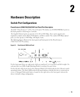
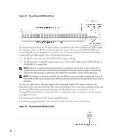
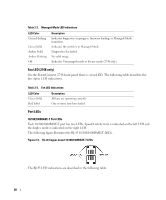
Table 2-2. Managed Mode LED Indications LED Color Green Flashing Green Solid Amber Solid Amber Flashing Off Description Indicates diagnostics in progress, firmware loading, or Managed Mode transition. Indicates the switch is in Managed Mode. Diagnostics has failed. No valid image. Indicates Unmanaged mode or Secure mode (2748 only). Fan LED (2748 only) On the PowerConnect 2748 front panel there is a fan LED. The following table describes the fan status LED indications. Table 2-3. Fan LED Indications LED Color Green Solid Red Solid Description All fans are operating correctly. One or more fans have failed. Port LEDs 10/100/1000BASE-T Port LEDs Each 10/100/1000BASE-T port has two LEDs. Speed/Link/Activity is indicated on the left LED and the duplex mode is indicated on the right LED. The following figure illustrates the RJ-45 10/100/1000BASE-T LEDs. Figure 2-9. RJ-45 Copper-based 10/100/1000BASE-T LEDs The RJ-45 LED indications are described in the following table: 20
-
 1
1 -
2
-
3
-
4
-
5
-
6
-
7
-
8
-
9
-
10
-
11
-
12
-
13
-
14
-
 15
15 -
 16
16 -
 17
17 -
 18
18 -
 19
19 -
 20
20 -
 21
21 -
 22
22 -
 23
23 -
 24
24 -
 25
25 -
26
-
27
-
28
-
29
-
30
-
31
-
32
-
33
-
34
-
35
-
36
-
37
-
38
-
39
-
40
-
41
-
42
-
43
-
44
-
45
-
46
-
47
-
48
-
49
-
50
-
51
-
52
-
53
-
54
-
55
-
56
-
57
-
58
-
59
-
60
-
61
-
62
-
63
-
64
-
65
-
66
-
67
-
68
-
69
-
70
-
71
-
72
-
73
-
74
-
75
-
76
-
77
-
78
-
79
-
80
-
81
-
82
-
83
-
84
 |
 |
