Dell PowerConnect 2708 User's Guide - Page 24
Pin Connections for SFP Interfaces, Power Connectors, Internal Power Supply Connector
 |
View all Dell PowerConnect 2708 manuals
Add to My Manuals
Save this manual to your list of manuals |
Page 24 highlights
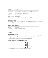
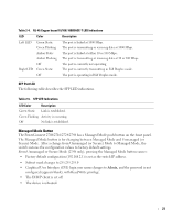
Pin Connections for SFP Interfaces Table 2-8. SFP Pin Connections Pin No Use 1 Transmitter ground (common with receiver ground) 2 Transmitter fault 3 Transmitter disable; laser output disabled on high or open. 4 Module definition 2; data line for serial ID. 5 Module definition 1; clock line for serial ID. 6 Module definition 0; grounded within the module. 7 Rate select; no connection required. 8 Loss of signal indication; logic 0 indicates normal operation. 9 Receiver ground (common with transmitter ground) 10 Receiver ground (common with transmitter ground) 11 Receiver ground (common with transmitter ground) 12 Receiver inverted data out; AC coupled. 13 Receiver non-inverted data out; AC coupled. 14 Receiver ground (common with transmitter ground) 15 Receiver power supply 16 Transmitter power supply 17 Transmitter ground (common with receiver ground) 18 Transmitter non-inverted data in 19 Transmitter inverted data in 20 Transmitter ground (common with receiver ground) Power Connectors The PowerConnect 2708/2716/2724/2748 switches are powered by using the AC internal power supply. Internal Power Supply Connector The PowerConnect 2708, PowerConnect 2716, PowerConnect 2724 and PowerConnect 2748 switch systems supports a single internal power supply to provide power for switching operations. The internal power supply supports input voltages between 100 and 240 VAC. The AC power connector is located on the back panel of the switch. 24
-
 1
1 -
2
-
3
-
4
-
5
-
6
-
7
-
8
-
9
-
10
-
11
-
12
-
13
-
14
-
15
-
16
-
17
-
18
-
 19
19 -
 20
20 -
 21
21 -
 22
22 -
 23
23 -
 24
24 -
 25
25 -
 26
26 -
 27
27 -
 28
28 -
 29
29 -
30
-
31
-
32
-
33
-
34
-
35
-
36
-
37
-
38
-
39
-
40
-
41
-
42
-
43
-
44
-
45
-
46
-
47
-
48
-
49
-
50
-
51
-
52
-
53
-
54
-
55
-
56
-
57
-
58
-
59
-
60
-
61
-
62
-
63
-
64
-
65
-
66
-
67
-
68
-
69
-
70
-
71
-
72
-
73
-
74
-
75
-
76
-
77
-
78
-
79
-
80
-
81
-
82
-
83
-
84
 |
 |
